Showing posts with label ic. Show all posts

Tuesday, November 18, 2014

FM Moulator with IC 555

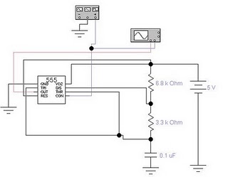
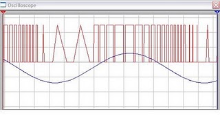
FM Modulator circuit is a simple FM modulation circuit using IC 555, where the resulting modulated signal has a tenuous meeting depends on the signal frequency information. 

FM

FM

The resulting signal can be spelled out quite nice and stable so that the result will be more perfect. No winding or inductor in series modulator, so you do not need to bother to make a winding and calculate the value of the coil that you created it. With this circuit the desired value of frequency modulation can be obtained easily by calculating the frequency of IC 555 in general, which is determined by the resistor 6.8 K and 3.3 K and 0.1 UF capacitor. To obtain the other frequencies of your stay replace one or all three components.

Actually fm modulator ic 555 circuit is very simple though, but I think it reliable enough to handle a simple application purposes that do not require a big power or a very high frequency. But if you want more power you can add the RF amplifier circuit at the output of this circuit. Thus, the results of modulated signal can be amplified with the help of a series of supporters. In accordance with my experimental series modulators can work well at frequencies below the MHz range, because it is not IC IC 555 which is devoted to support of a very high frequency. You can use oscilltor transistor circuit, XTAL or others if you need a very high frequency.

The difference circuit with IC 555 on the multivibrator circuit in general is the use of pin 5, on the FM Modulator circuit is pin 5 of IC 555 is used as input information signal, which in turn will influence the shape of the output signal (modulated). But in applying this 5 pin multivibrator functions normally associated with 0.01 UF capacitor or left alone.
Read More..

Friday, November 7, 2014

IC 555 Design Note

The popular Timer IC 555 is extensively used in short duration timing applications. IC 555 is a highly stable integrated circuit functioning as an accurate time delay generator and free running multivibrator. But one of the serious problem in 555 timer design is the false triggering of the circuit at power on or when voltage changes. The article describes how IC555 is designed perfectly to avoid false triggering.555 IC pin functionsPin1 Ground
Pin2 Trigger
Pin3 Output
Pin 4 Reset
Pin 5 Control voltage
Pin 6 Threshold
Pin 7 Discharge
Pin 8 VccFunctional aspects of pinsTrigger Pin 2Usually pin2 of the IC is held high by a pull up resistor connected to Vcc. When a negative going pulse is applied to pin 2, the potential at pin 2 falls below 1/3 Vcc and the flip-flop switches on. This starts the timing cycle using the resistor and capacitor connected to pins 6 and 7.Reset pin 4Reset pin 4 can be controlled to reset the timing cycle. If pin 4 is grounded, IC will not be triggered. When pin4 becomes positive, IC becomes ready to start the timing cycle. Reset voltage is typically 0.7 volts and reset current 0.1 mA. In timer applications, reset pin should be connected to Vcc to get more than 0.7 volts.Control Voltage pin 5Pin5 can be used to control the working of IC by providing a DC voltage at pin5. This permits the control of the timing cycle manually or electronically. In monostable operation, the control pin5 is connected to ground through a 0.01 uF capacitor. This prevents the timing interval from being affected by AC or RF interference. In the Astable mode, by applying a variable DC voltage at pin 5 can change the output pulses to FM or PWM.Threshold pin 6 and Discharge pin 7These two inputs are used to connect the timing components- Resistor and Capacitor. The threshold comparator inside the IC is referenced at 2/3 Vcc and the trigger comparator is referenced at 1/3 Vcc. These two comparators control the internal Flip-Flop of the circuit to give High or Low output at pin 3.When a negative going pulse is applied to pin 2, the potential at pin2 drops below 1/3 Vcc and the trigger comparator switches on the Flip-Flop. This turns the output high. The timing comparator then charges through the timing resistor and the voltage in the timing capacitor increases to 2/3 Vcc.( The time delay depends on the value of the resistor and capacitor.

That is, higher values, higher time).When the voltage level in the capacitor increases above 2/3 Vcc, the threshold comparator resets the Flip-Flop and the output turns low. Capacitor then discharges through pin 7.Once triggered, the IC will not responds to further triggering until the timing cycle is completed. The time delay period is calculated using the formula T= 1.1 Ct Rt. Where Ct is the value of Capacitor in PF and Rt is the value of Resistor in Ohms. Time is in Seconds.How to eliminate false triggering?The circuit diagram shown below is the simple monostable using IC 555. To eliminate the false triggering resistor R1 and Capacitor C1 are connected to the reset pin 4 of the IC. So the reset pin is always high even if the supply voltage changes. Moreover capacitor C3 connected close to the Vcc pin 8 acts as a buffer to maintain stable supply voltage to pin 8. Using this design, it is easy to avoid false triggering to a certain extent.

555 Monostable circuit

A ready recknor to select timing resistor and capacitor
Theoretically long interval is possible with IC 555,but in practical conditions, it is difficult to get more than 3 minutes. If low leakage Tantalum capacitor is used, this can be increased to 5 minutes or more. If the value of the timing capacitor is too high above 470 uF, charging time will be prolonged which will upset the timing cycle and the output remains high even after the desired time is over.
Read More..

Thursday, September 25, 2014

Electronic Voltmeter Ammeter Circuit Using Single IC 741

Simple Electronic Multimeter  High cost deters many hobbyists from buying a conventional multimeter. Since it is difficult to obtain cheap 50 uAor 100uA meters which are essential for a highly sensitive multimeter, an electronic alternative device is suggested to serve the purpose. The circuit shown here gives economic and safe ranges covered to three values : (i) 0-15V, (ii) 0- l5mA, and (iii) 0-150mA.
The ranges can be extended with suitable modifications. The 741 operational amplifier acts as a null detector. its output is equal to the voltage at point A minus the voltage at , point B, multiplied by the device’s very high voltage gain. lf VA is slightly greater than VB, the output is limited by the supply voltage to about 7 volts. lf  VA is slightly less than VB, the output is about 2 volts. At the point at which the output changes from low to high or vice-versa, VA is equal to VB to within a very small margin of error. With the switch set to the position shown in circuit diagram (15V range) the potential difference between points A and C is

R3+R4+R5/R1+R2+R3+R4+R5 * input voltage

or 1/30 * input voltage


 The forward voltage drop of the diode D3 is about 0.6V and largely independent of battery condition. About 0.5V appears across the variable resistance VRl and a known fraction of this indicated by a scale on the potentiometer appears between points A and C, i.e. it compares the known reference voltage with a known fraction of the input voltage. On the two current ranges, the reference potential difference is compared with the voltages developed across R4 plus R5 on the l5mA range and R5 only in 150mA range. T D2, a light emitting diode, with its current limiting series resistor R9 indicates whether the output of the operational amplifier is high or low. The diode D1 and the condenser Cl provide the facility of measuring alternating voltages and  currents. lf the voltage at A momentarily exceeds the voltage at B, then Cl will charge up via Dl maintaining D2»alight until the peak of the next cycle. Without Cl there is no sharp point at which D2 extinguishes for AC measurement. ln use it must be remembered that the indicated readings are all peak values and will thus need to be divided by square-root of 2 to give RMS value for a sinusoidal input. The meter is calibrated directly VRl is scaled 0-15 on the _ 15V range by comparison with a standard meter. This calibration will hold quite closely for current ranges—the agreement depending on the tolerances of Rl to R5. Ten per cent tolerance resistors have been found to be quite successful for these but, if desired, 5 or even 2 per cent resistors provide a worthwhile increase in the accuracy of the current ranges. ln use, the meter is switched to the appropriate range and V connected as for a conventional multimeter. The potentiometer VR] is rotated until D2 is at the point of changing from off to on and then the reading is directly indicated. on the potentiometer scale. The diodes may be any silicon diode. For use of the multimeter in 0- l 50V range, the values of the resistors Rl to R5 may be changed proportionately so that the value of the ratio

R3+R4+R5/R1+R2+R3+R4+R5

is l/300. Then with these values, the multimeter will operate on 0- l 5OV range in the first position (as shown in the existing diagram). The accuracy no doubt will be somewhat ham- pered. VRl has to be calibrated accordingly.

Electronic voltmeter, ammeter circuit using a single IC 741

Read More..

Monday, September 15, 2014

Stereo Power Amplifier Using IC 7905

79xx is a widely known series of low-cost, fixed-negative-voltage regulators. These integrated diagram are available with output current of 100-150 mA (L series), 0.4-0.5A (M series), up to 1A (standard series), etc. They can be used in many applications other than regulators, audio power amplifier being one of them.  As shown in the schema diagram, a simple stereo audio amplifier is built around two 7905 negative-voltage regulators (IC1 and IC2) and a few discrete components. The 7905 IC (a -5V regulator) used here is readily available. However, the schema will also work with other 79XX regulators if appropriate power supply is used. Both channels shown in the diagram are identical. Hence the description below is only for the first channel. The quality of the output signal is within acceptable limits. 

Circuit diagram :
Stereo-Power-Amplifier
Stereo Power Amplifier Circuit Diagram
 
Regulator IC 7905 works as an amplifier for the voltages applied to common pin2 (Ground or GND). The minimal voltage drop over the standard 7905 is around 2V and it depends on the output current. Feedback resistors in the IC set the gain of the channel internally. The amplifier is a class-A audio amplifier. The regulator IC produces the negative output signal. 

Resistor R3 provides the positive signal. It limits the maximum output current of the regulator during the negative half period of the amplified sinusoidal signal. The minimal applicable value of R3 for the regulator 7905 is 8.2 to 10 ohms per 5W.  Optimisation of the value of R3 depends on the output voltage of the regulator, negative power supply (–5V) and load resistance of loudspeaker (LS1). If the required output current for LS1 is below 100 mA, the value of resistor R3 can be 33 to 51 ohms per watt. 

Normally, the load resistance of the loudspeaker should be higher than of R3 in order to obtain a large peak-to-peak amplitude. But this can be neglected in order to obtain lower power dissipation on R3 and the IC. The schema works with any load resistance (R3 in parallel with LS1 as the load) under the condition that the regulator is not overloaded with current and power dissipation. However, it is preferable to use a loudspeaker with a high resistance (8 ohms, 16 ohms or more). The amplifier works well with low-impedance headphones having a resistance of 24 to 32 ohms. The voltage difference between the ground pin of 7905 and the output pin is fixed internally. 

The input resistance of the amplifier is relatively low and depends on potentiometer VR1 and input resistance of the ground pin. Practically, any stereo output capable of driving 24- or 32-ohm headphones and loudspeakers can drive the input of the stereo amplifier with 7905. If VR1 is removed, the amplifier will still work but there will be more distortion. Therefore potentiometer VR1 is used to provide sufficient variable audio signal.  The values of output capacitors C10 and C11 are usually between 0.1 µF and 1 µF. A small resistance can be connected in series with them if needed. S2 is the on/off switch. Switch S1 is for mono/stereo selection. When switch S1 is closed, the amplifier works as a two-way mono amplifier. If S1 is open, the amplifier works as a stereo amplifier. 

The schema is powered by a 12V battery. The positive terminal of the battery is the common node. The negative terminal is connected to pin 2 of IC1, which is the –12V supply line. The maximum operating voltage can be up to –35V. If no input signal is applied, the DC voltage on the output of the regulator 7905 should be around –5V, which depends to some extent on the value of VR1. The maximum output current of 7905 can be up to 1A and the maximum power dissipation is up to 15W. IC 7905 has internal thermal protection. 

Assemble the schema on a general-purpose PCB and enclose in a suitable cabinet. Fix the stereo female jack on the front panel and speaker to the rear side of the cabinet, and the 12V battery inside the cabinet. Fix LED1 and switches S1 and S2 too on the front panel of the cabinet. Mount the regulator IC 7905 on a heat-sink with thermal resistance below 15°C/W. The metallic part on the case is internally connected with the input pin of the regulator.

Author : Petre tzv. Petrov Sourced by: EFy
Read More..

Wednesday, September 10, 2014

Simple Subwoofer Lowpass Filter using uA741 Single Op Amp Ic

This is the simplest Sub woofer Low Pass filter Circuit using uA741 single op amp ic. The schema is very low cost with respect to their work. The cut off frequency of this schema is 25Hz to 80Hz maximum. Using this schema , you can easily design a 2.1 Sub-woofer Speaker System at your own Home. The schema contains very few components.In Pakistan, the cost of this schema with PCB is Rs:45 The same schema is working in my own hand made sub-woofer system. So Try this [Link]

Lowpass

Parts List: 

R1,R3,R4 = 10K 1/4W
R2=100K 1/4W
CY1,CY2 = 0.22uF Polyester
C1,C2 = 10uF/25V Electrolytic
IC1 = uA741A Single Op-Amp Ic + 8 Pin Ic Socket
3 Pin Male & Female Connector x 2
2 Pin Male & Female Connector x 1
PCB as in required size 4.5 cm x 3.4 cm
Read More..

Thursday, September 4, 2014

Multiplexer with CMOS IC 4556

In addition to the family of TTL ICs that support the function of a multiplexer is a family of CMOS ICs.

Despite the fact it is the family of TTL ICs that support more functions than the CMOS multiplexer. For the working principle of the multiplexer IC CMOS family is actually tantamount to a multiplexer circuit, or IC TTL logic gates. That should be all referring to the real multiplexer function, namely the determination of output lines which represent the number of input lines. The use of symbols is possible between TTL and CMOS IC has a different but actually run the same rules. For your reference if you are interested in using family of CMOS IC 4556 series in particular, I include also the truth table below:


INPUT
OUTPUT
E
A0
A1
O0
O1
O2
O3
L
L
L
L
H
H
H
L
H
L
H
L
H
H
L
L
H
H
H
L
H
L
H
H
H
H
H
L
H
X
X
H
H
H
H
L = LOW
H = HIGH
Read More..

Monday, September 1, 2014

Car amplifier circuit with IC BA532

Minimum Voltage required for this circuit 6 volt and maximum voltage 18 volt . Its can use to amplifier on the electronic devices such us Radio , DVD , MP4 , MP5 , and etc. To amplify the signal sound to audio sound , If you want to bring amplfier you can use the 6V rechargeable battery is able to turn it. What use the rechargeable battery ? because with rechargeable battery when battery runs out , you can charge back.
See Amplifier schematic with IC BA511 below :

Maximum output power 10 Watt with impedance 4 ohm. The circuit is mono amplifier. You can use the circuit to caramplifier because support to low power subwoofer speaker
Read More..

Wednesday, August 27, 2014

9 Volt Power Supply Wiring diagram Schematic Using IC 7809

Description
Circuit showing a 9 volt power supply . Here we have used a bridge rectifier and 7809 ic for making this schema.Where the ic regulate the output to 9 v,1 A .This voltage every time constant.Are you interested ?

Circuit diagram with Parts list. 


Notes. 
  • If a current of 300 mA or above is required, fit a proper heat sink to the IC 7809.
  • If 1A bridge is not available, make one using four 1N 4007 diodes.
Read More..

Saturday, August 9, 2014

One IC Led Flasher circuit Wiring diagram

Most of people always send emails to Free Circuit Diagrams 4U asking simple Circuit diagrams. Here Im going to give you a very simple flasher schema diagram the specialty of this schema is we can operate this schema with 1.5 V power supply.And we have used only one IC for this schema that means you need to buy only three parts to build up this schema.Here we have used common IC3909.


Note : 
         # Build this schema on a PCB
         # Dont supply over 1.5V
Read More..