Sunday, September 21, 2014
Simple LED Torch
A common problem with small torches is the short life-span both of the batteries and the bulb. The average incandescent torch, for instance, consumes around 2 Watts. The LED Torch in Fig. 1 consumes just 24 mW, giving it more than 80 times longer service from 4 AA alkaline batteries (that is, up to one months continuous service). Although the torchs light output is modest, it is nonetheless quite sufficient to illuminate a pathway for walking.
Circuit Diagram :
Fig. 1 : Simple LED Torch Circuit Diagram
The LED Torch is based on a 7555 timer running in astable mode (do not use an ordinary 555). A white LED (Maplin order code NR73) produces 400 mcd light output, which, when focussed, can illuminate objects at 30 metres. Try Conrad Electronic for what appears to be a stronger white LED (order code 15 37 45-11). A convex lens with short focal length is placed in front of the LED to focus the beam. If banding occurs at the beams perimeter, use another very short focal length lens directly in front of the LED to smooth the beam.
If a different supply voltage is preferred, the value of resistor R3 is modified as follows:
9V - 470 Ohm12V - 560 Ohm
See my "Wind-up Torch" feature article in the October 2000 edition of Everyday Practical Electronics for a completely battery-free go-everywhere torch.

Wednesday, September 10, 2014
Simple LED light Organ Wiring diagram Schematic
LED light Organ Circuit Diagram
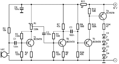
The 4 Budget
This schema costs about € 6.15.
Parts List
- R1 = 10 k
- R2 = 330 K?
- R3, R6, R13 = 100 k
- R4, R8, R11, R14 = 47 Ω
- R5, R9, R12 = 1.5 MΩ
- R7, R10 = 47 k
- P1 = 220 K?
- C1, C2, C3 = 100 nF
- C4 = 100 uF
- D1-D4 = LED
- T1, T2, T3 = BC547B
- T4 = BC557B
- MIC = microphone capsule
Monday, September 8, 2014
Constant LED Power Supply Wiring diagram Schematic
Saturday, August 16, 2014
LED Light Pen Wiring diagram Schematic
LEDs have a much longer life than bulbs and the latest ultra bright white ones also offer higher energy-to-light conversion efficiency. On the down side, LEDs require a small electronic helper schema called ‘constant-current source’ to get the most out of them.
LED Light Pen Circuit Diagram

Here, T1 and R1 switch on the LED. R2 acts as a current sensor with T2 shunting off (most of) T1’s base bias current when the voltage developed across R2 exceeds about 0.65 V. The constant current through the white LED is calculated from
R2 = 0.65 / ILED
With some skill the complete schema can be built such that its size is equal to an AA battery. The four button cells take the place of the other AA battery that used to be inside the light pen. Link
Thursday, August 14, 2014
First LED lamp that replaces a 100 watt incandescent

Saturday, August 9, 2014
One IC Led Flasher circuit Wiring diagram


Note :
# Build this schema on a PCB
# Dont supply over 1.5V
