Showing posts with label light. Show all posts

Wednesday, September 10, 2014

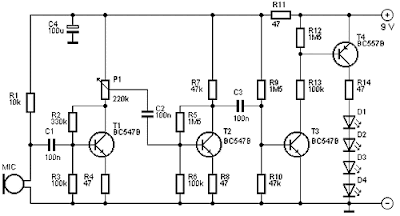
Simple LED light Organ Wiring diagram Schematic

This is a Simple LED light Organ Circuit Diagram. This is a fun schema that can be at parties, for example. The four LEDs flash to the beat of the music. The light organ responds using a microphone to sound.T1 amplifies the signal from MIC. The sensitivity can be adjusted by P1. T4 controls the LEDs. 

These are preferably LEDs with a high light intensity.MIC is a condenser microphone. The schema can be powered by a 9 V battery.

 LED light Organ Circuit Diagram

 led light organ circuit diagram


The 4 Budget

This schema costs about € 6.15.


Parts List

  •      R1 = 10 k
  •      R2 = 330 K?
  •      R3, R6, R13 = 100 k
  •      R4, R8, R11, R14 = 47 Ω
  •      R5, R9, R12 = 1.5 MΩ
  •      R7, R10 = 47 k
  •      P1 = 220 K?
  •      C1, C2, C3 = 100 nF
  •      C4 = 100 uF
  •      D1-D4 = LED
  •      T1, T2, T3 = BC547B
  •      T4 = BC557B
  •      MIC = microphone capsule
Read More..

Monday, September 8, 2014

Courtesy Light

This schema is intended to let the user turn off a lamp by means of a switch placed far from bed, allowing him enough time to lie down before the lamp really switches off.
Obviously, users will be able to find different applications for this schema in order to suit their needs.


Lamp


Parts:

R1____________470R 1/2W Resistor
R2____________100K 1/4W Resistor
R3______________1M5 1/4W Resistor
R4______________1K 1/4W Resistor

C1____________330nF 400V Polyester Capacitor
C2____________100µF 25V Electrolytic Capacitor
C3,C5__________10nF 63V Polyester or Ceramic Capacitors
C4_____________10µF 25V Electrolytic Capacitor

D1,D2________1N4007 1000V 1A Diodes
D3_________BZX79C10 10V 500mW Zener Diode
D4__________TIC206M 600V 4A TRIAC

Q1____________BC557 45V 100mA PNP Transistor

IC1____________7555 or TS555CN CMos Timer IC

SW1____________SPST Mains suited Switch


Due to the low current drawing, the schema can be supplied from 230Vac mains without a transformer. Supply voltage is reduced to 10Vdc by means of C1 reactance, a two diode rectifier cell D1 & D2 and Zener diode D3. IC1 is a CMos 555 timer wired as a monostable, providing 15 seconds on-time set by R3 & C4. When SW1 is closed, IC1 output (pin 3) is permanently on, driving Triac D4 which in turn feeds the lamp. Opening SW1 operates the monostable and, after 15 seconds, pin 3 of IC1 goes low switching off the lamp.

Notes:

* The schema is wired permanently to the mains supply but current drain is negligible.
* Due to transformerless design there is no heat generation.
* The delay time can be varied changing R3 and/or C4 values.
* Taking C4 = 10µF, R3 increases timing with about 100K per second ratio. I.e. R3 = 1M Time = 10 seconds, R3 = 1M8 Time = 18 seconds.
* Low Gate-current Triacs are recommended.
* Use a well insulated mains-type switch for SW1.
* Warning! The schema is connected to 230Vac mains, then some parts in the schema board are subjected to lethal potential!. Avoid touching the schema when plugged and enclose it in a plastic box.


Read More..

Thursday, September 4, 2014

Night security light


Here is a simple schema switches on a light around 2 hours after midnight, the time at which most of the robberies taking place.


This simple schema is build around a CMOS IC 4060 to obtain the required timing. During day time the LDR has low resistance and keeps the pin 12 of the IC1 high, preventing the IC1 from oscillating. When it is dark the LDR resistance becomes high and the pin 12 of IC1 becomes low and the IC starts oscillating, which indicated by the flashing of LED D3.The values of the timing components R1, R2, C4 are so selected that the out put pin3 of IC1 goes high after 8 hours. That means the high output drives the triac to switch on the lamp around 2’O clock. At morning, the LDR resistance drops and the pin 12 of IC1 goes high and stops the oscillation, making the lamp OFF. The switch S1 can be used to manually ON the lamp. The capacitor C2 prevents false triggering.


Notes.

* Assemble the schema on a good quality PCB or common board.
* The LDR can be general purpose LDR.
* The light sensitivity can be adjusted using the preset R6.
* The IC1 must be mounted on an IC holder.

Read More..

Tuesday, September 2, 2014

12v Light Dark Switch Wiring diagram Schematic

Often, for certain low voltage lighting systems; you would like to turn off the lights during the bright light of the day.  Most commercial day/night switches are designed for AC lighting.  This hobby schema below was designed for a 12v DC system.  But, it could be modified for other voltage as well.  It uses an inexpensive photo-transistor as the light detector.  An n-channel FET is used to switch power to the lights.  A transistor schema is included to provide some hysteresis.  

This keeps the schema from fluttering the light during the transition from day to night and night to day.  It is recommended that a plastic tube be placed over the transistor to prevent it from being illuminated by the lights it is controlling.  By selecting the appropriate power FET, the schema could control over 100 watts worth of 12v lighting.   (July 22, 2008)


Circuit


Source: DiscoverCircuits
Read More..

Saturday, August 23, 2014

Build a Solar Garden Light Wiring diagram Schematic

This is a Solar Garden Light Circuit Diagram that consists of a very simple system garden lighting that can be done by using some common electronic parts and a small solar panel. The electronic design is simple yet very efficient, has the advantage of being solar powered, it requires only one transistor, one 2.5 volt solar panel and some other common electronic components you can remove junk. 

This solar lighting system automatically turns on the LEDs when the solar panel detects no light turns off when the solar panel produces more than 1v and charges the battery when the panel produces more than 2.1V

The coils in this schema require a core material F29 and they must be made with wire of 0.095 mm in core 2.6x6mm. "This schema uses the system joule thief (joule thief) to provide voltage necessary for the LED, so other coils can be tested.

Solar Garden Light Circuit Diagram

Solar

Read More..

Thursday, August 21, 2014

Electronic Components As Light Sensor

Electronic Components As Light Sensor

Electronic components are included in the category of light sensors is LDR, Photo Transistor, Photo Diode, Infrared Receiver. The function of the electronic component is to detect the intensity of light received by the component. The light sensor is often used in electronic equipment such as on television, light a light switch, light intensity measuring instrument.

Electronic
Electronic Components As Light Sensor 
Read More..

Saturday, August 16, 2014

LED Light Pen Wiring diagram Schematic

Physicians and repair engineers often use small light pens for visual examination purposes. Rugged and expensive as these pens may be, their weak point is the bulb, which is a ‘serviceable’ part. In practice, that nearly always equates to ‘expensive’ and / or ‘impossible to find’ when you need one.

LEDs have a much longer life than bulbs and the latest ultra bright white ones also offer higher energy-to-light conversion efficiency. On the down side, LEDs require a small electronic helper schema called ‘constant-current source’ to get the most out of them.
 
LED Light Pen Circuit Diagram
LED-Light-Pen-Circuit-Diagram

Here, T1 and R1 switch on the LED. R2 acts as a current sensor with T2 shunting off (most of) T1’s base bias current when the voltage developed across R2 exceeds about 0.65 V. The constant current through the white LED is calculated from

R2 = 0.65 / ILED
With some skill the complete schema can be built such that its size is equal to an AA battery. The four button cells take the place of the other AA battery that used to be inside the light pen. Link


Author: Myo Min – Copyright: Elektor
Read More..

Monday, August 11, 2014

Light Operated Rellay Circuit diagram


This is light operated schema diagram.Wonderful thing is this schema can be operated with 9V power supply.You can attach this schema for your vehicle even.I have used this schema for my car as an automatic dim switch.This schema operates with BC548 Transistor.If you want more info you can send us an email through our website email address.


Note

# Fix this schema on a P.C.B

# Dont use more than 9V
Read More..