Wiring Material
Monday, January 26, 2015
Low Cost Guitar Amplifier
The aim of this design was to reproduce a Combo amplifier of the type very common in the sixties and the seventies of the past century. It is well suited as a guitar amplifier but it will do a good job with any kind of electronic musical instrument or microphone. 5W power output was a common feature of these widespread devices due to the general adoption of a class A single-tube output stage (see the Vox AC-4 model). Furthermore, nowadays we can do without the old-fashioned Vib-Trem feature frequently included in those designs.
The present circuit can deliver 10W of output power when driving an 8 Ohm load, or about 18W @ 4 Ohm. It also features a two-FET preamplifier, two inputs with different sensitivity, a treble-cut control and an optional switch allowing overdrive or powerful treble-enhancement.
The present circuit can deliver 10W of output power when driving an 8 Ohm load, or about 18W @ 4 Ohm. It also features a two-FET preamplifier, two inputs with different sensitivity, a treble-cut control and an optional switch allowing overdrive or powerful treble-enhancement.
Guitar Amplifier Circuit Diagram
P1______________4K7 Linear Potentiometer
P2_____________10K Log. Potentiometer
R1,R2__________68K 1/4W Resistors
R3____________220K 1/4W Resistor
R4,R6,R11_______4K7 1/4W Resistors
R5_____________27K 1/4W Resistor
R7______________1K 1/4W Resistor
R8______________3K3 1/2W Resistor
R9______________2K 1/2W Trimmer Cermet
R10___________470R 1/4W Resistor
R12_____________1K5 1/4W Resistor
R13___________470K 1/4W Resistor
R14____________33K 1/4W Resistor
C1____________100pF 63V Ceramic Capacitor
C2____________100nF 63V Polyester Capacitor
C3____________470µF 35V Electrolytic Capacitor
C4____________220nF 63V Polyester Capacitor (Optional, see Notes)
C5_____________47µF 25V Electrolytic Capacitor (Optional, see Notes)
C6______________1µF 63V Polyester Capacitor
C7,C8,C9,C10___47µF 25V Electrolytic Capacitors
C11____________47pF 63V Ceramic Capacitor
C12__________1000µF 35V Electrolytic Capacitor
C13__________2200µF 35V Electrolytic Capacitor
D1_____________5mm. Red LED
D2,D3________1N4004 400V 1A Diodes
Q1,Q2________2N3819 General-purpose N-Channel FETs
Q3____________BC182 50V 200mA NPN Transistor
Q4____________BD135 45V 1.5A NPN Transistor (See Notes)
Q5____________BDX53A 60V 8A NPN Darlington Transistor
Q6____________BDX54A 60V 8A PNP Darlington Transistor
J1,J2________6.3mm. Mono Jack sockets
SW1____________1 pole 3 ways rotary switch (Optional, see Notes)
SW2____________SPST Mains switch
F1_____________1.6A Fuse with socket
T1_____________220V Primary, 48V Center-tapped Secondary 20 to 30VA Mains transformer
PL1____________Male Mains plug
SPKR___________One or more speakers wired in series or in parallel, Total resulting impedance: 8 or 4 Ohm, Minimum power handling: 20W
Notes:
- SW1 and related capacitors C4 & C5 are optional.
- When SW1 slider is connected to C5 the overdrive feature is enabled.
- When SW1 slider is connected to C4 the treble-enhancer is enabled.
- C4 value can be varied from 100nF to 470nF to suit your treble-enhancement preferences.
- In all cases where Darlington transistors are used as the output devices it is essential that the sensing transistor (Q4) should be in as close thermal contact with the output transistors as possible. Therefore a TO126-case transistor type was chosen for easy bolting on the heatsink, very close to the output pair.
- To set quiescent current, remove temporarily the Fuse F1 and insert the probes of an Avo-meter in the two leads of the fuse holder.
- Set the volume control to the minimum and Trimmer R9 to its minimum resistance.
- Power-on the circuit and adjust R9 to read a current drawing of about 25 to 30mA.
- Wait about 15 minutes, watch if the current is varying and readjust if necessary.
Sensitivity:
30mV input for 10W output
Frequency response:
40 to 20KHz -1dB
Total harmonic distortion @ 1KHz and 10KHz, 8 Ohm load:
below 0.05% @ 1W, 0.08% @ 3.5W, 0.15% at the onset of clipping (about 10W).
Friday, December 12, 2014
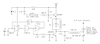
Broadcast Transmitter Circuit Diagram

In this circuit, a 74HC14 hex Schmitt trigger inverter is used as a square wave oscillator to drive a small signal transistor in a class C amplifier configuration.The oscillator frequency can be either fixed by a crystal or made adjustable (VFO) with a capacitor/resistor combination.
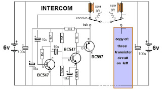
Intercom Circuit with Transistors

This is a 2-station simple intercom circuit build based on transistors part and using common 8R mini speakers. The speaker works as microphone and generate sound, so there is no need microphone for this intercom. The "press-to-talk" switches should have a spring-return so the intercom can never be left ON, push on switch can be used for this kind of task.
Voltage inverter circuit
This voltage inverter circuit powering a dual supply op amp from a single battery problem. The circuit simply takes a positive voltage and inverts it. It uses only one 555 timer and a few other passive components, so it doesn't add much in the way of size and cost to a project.
Thursday, December 11, 2014
Voltage Inverter Circuit

This simple and inexpensive circuit can produce a dual (positive and negative) voltage from a single supply input.
It is therefore extremely useful for powering opamp and other circuits that require a dual voltage from a single battery.
Thursday, November 20, 2014
555 basic PWM controller
IC Timer 555 has a basic PWM controller with features pengendalianlebar 0 .. 100% pulse that is controlled using the R1, at the time of controlling the oscillator frequency relatively stabi so it may be used to build the Simple PWM controller. Frequency of Simple PWM controller 555 depending on the value of R1 and C1, values shown R1 and C1 will form the output with a frequency of 170 to 200 Hz. Diode-diode used in the Simple PWM controller With this 555 can use a 1N4148.
![555]()
Read More..
R2, R3 and C3 form a giver triger circuit beginning at the reset IC 555 for 2 seconds. If you want to use a series of Simple PWM controller 555 with the V + not +12 V, it does not matter to raise tilapia R2 where (V + * R2) / (R2 + R3) is about 2, because it limits the signal level reset is 0.5 .. 1V. If you do not do that, then signal the kickstart to get too close to the limit reset signal reception.
Q output of 555 on the Simple PWM controller circuit 555 is used for driver PWM pulse, so that the discharge pin is used for transistor output driver instead. This is an open collector output, and is used as an active signal is low, so it can work. D3 protects the output transistor of the load induction. You may replace any suitable transistors for Q1, BD140 is 1.5 amps.
C4 and C5 is the power decoupling capacitor for the IC 555 on the Simple PWM controller circuit 555, which produce relatively large level of push-pull output stage.
20W Car Audio Amplifier with LM1875
The IC is aswell arranged with a lot acceptable appearance like fast bulk rate, advanced accumulation voltage range, top achievement current, top achievement voltage swing, thermal aegis etc. The IC is accessible in TO-220 artificial ability amalgamation and is able-bodied acceptable for a array of applications like audio systems, servo amplifiers, home theatre systems etc.
Notes.
- Assemble the circuit on a good quality PCB.
- Use +/-25V DC dual supply for powering the circuit.
- K1 can be 4 ohm, 20W speaker.
- A proper heat sink is necessary for the IC.
- F1 and F2 are 2A
Subscribe to:
Comments (Atom)