Showing posts with label intercom. Show all posts
Showing posts with label intercom. Show all posts
Friday, December 12, 2014
Intercom Circuit with Transistors
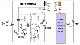
This is a 2-station simple intercom circuit build based on transistors part and using common 8R mini speakers. The speaker works as microphone and generate sound, so there is no need microphone for this intercom. The "press-to-talk" switches should have a spring-return so the intercom can never be left ON, push on switch can be used for this kind of task.

Saturday, August 30, 2014
Video Switch for Intercom System Wiring diagram Schematic
Simple and easy Video Switch for Intercom System Circuit Diagram. Nowadays a lot of intercom units are equipped with video cameras so that you can see as well as hear who is at the door. Unfortunately, the camera lens is perfectly placed to serve as a sort of support point for people during the conversation, with the result that there’s hardly anything left see in the video imagery. One way to solve this problem is to install two cameras on the street side instead only one, preferably some distance apart. If you display the imagery from the two cameras alternately, then at least half of the time you will be able to see what is happening in front of the door. Thanks to the video switch module described here, which should be installed on the street side not too far away from the two cameras, you need only one monitor inside the house and you don’t need to install any additional video cables.
Circuit diagram :
Video Switch for Intercom System Circuit Diagram
Along with a video switch, the schema includes a video amplifier that has been used with good results in many other Elektor projects, which allows the brightness and the contrast to be adjusted separately. This amplifier is included because the distance between the street and the house may be rather large, so it is helpful to be able to compensate for cable attenuation in this manner. The switch stage is built around the well known 4060 IC, in which switches IC2a and IC2d alternately pass one of the two signals to the output. They are driven by switches IC2b and IC2c, which generate control signals that are 180 degrees out of phase. The switching rate for the video signals is determined by a clock signal from an ‘old standby’ 555 IC, which causes the signals to swap every 2 seconds with the specified com ponent values.
Naturally, this schema can also used in many other situations, such as where two cameras are needed for surveillance but only one video cable is available.
http://streampowers.blogspot.com/2012/06/video-switch-for-intercom-system_11.html
Sunday, August 10, 2014
Simple Intercom Circuit diagram

This is a intercom schema diagram.you can use this for your office or for your working place.Acoording to the changes of s1a and s1b You can use this as the reciever and the mic

Note
# Use screen wires Between these two diagram
Subscribe to:
Posts (Atom)
