Showing posts with label load. Show all posts
Showing posts with label load. Show all posts
Monday, August 25, 2014
Discharge the large electrolytic capacitor load
If the switching regulator fails to work or fail to start, then it is usually of the electrolytic capacitor is storing charge. There are habits of some engineers dumping electrolyte capacitor like this using solder. This is actually a poor habit. Because without them knowing things like this sometimes can lead to broken solder element.
Why this may happen?
Another bad habit of throwing of the electrolytic capacitor is to download shortkan legs electrolyte capacitor with a screwdriver. It is no possibility of damaging electrolytic capacitor itself, in which connection leg electrolyte capacitor is no risk in it will burn.
How should the dumping of the electrolytic capacitors?
- Always provide a resistor with a value of about 30k ~ 50k/2w
- If the correct power supply to the problem fails to work, then the resistor is normally for a while we solder directly on the legs of of the electrolytic capacitor. And if the problem is ok, the new resistor is removed.

Sunday, August 10, 2014
Simple Automatic Load Sensing Power Switch
This schema will automatically switch on several mains-powered "slave" loads when a "master" load is turned on. For example, it will switch on the amplifier and CD player in a stereo system when the receiver is turned on. It works by sensing the current draw of the "master" device through a low value high wattage resistor using a comparator. The output of that comparator then switches on the "slave" relay. The schema can be built into a power bar, extension cord or power center to provide a convenient set of "smart" outlets that switch on when the master appliance is powered (turn on the computer monitor and the computer, printer and other peripherals come on as well).
.
Simple Automatic Load Sensing Power Switch Circuit Diagram
.
Simple Automatic Load Sensing Power Switch Circuit Diagram
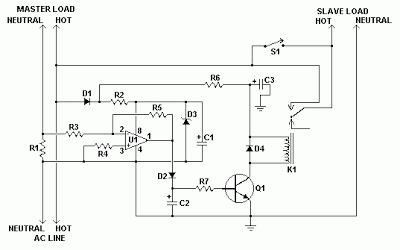
Parts
| C1, C3 | 2 | 10uF 35V Electrolytic Capacitor | |
| C2 | 1 | 1uF 35V Electrolytic Capacitor | |
| R1 | 1 | 0.1 Ohm 10W Resistor | |
| R2 | 1 | 27K 1/2W Resistor | |
| R3, R4 | 1 | 1K 1/4W Resistor | |
| R5 | 1 | 470K 1/4W Resistor | |
| R6 | 1 | 4.7K 1/2W Resistor | |
| R7 | 1 | 10K 1/4W Resistor | |
| D1, D2, D4 | 3 | 1N4004 Rectifier Diode | |
| D3 | 1 | 1N4744 15V 1 Watt Zener Diode | |
| U1 | 1 | LM358N Dual Op Amp IC | |
| Q1 | 1 | 2N3904 NPN Transistor | |
| K1 | 1 | Relay, 12VDC Coil, 120VAC 10A Contacts | |
| S1 | 1 | SPST Switch 120AVC, 10A | |
| MISC | 1 | Board, Wire, Socket For U1, Case, Mains Plug, Socket |
Notes
- This schema is designed for 120V operation. For 240V operation, resistors R2 and R6 will need to be changed.
- A maximum of 5A can be used as the master unless the wattage of R1 is increased S1 provides a manual bypass switch.
- THis schema is not isolated from the mains supply. Because of this, you must exercise extreme caution when working around the schema if it is plugged in.
Subscribe to:
Posts (Atom)
