Showing posts with label automatic. Show all posts
Showing posts with label automatic. Show all posts
Wednesday, September 17, 2014
Automatic Heat Detector
This circuit uses a complementary pair comprising npn metallic transistor T1 (BC109) and pnp germanium transistor T2 (AC188) to detect heat (due to outbreak of fire, etc) in the vicinity and energise a siren. The collector of transistor T1 is connected to the base of transistor T2, while the collector of transistor T2 is connected to relay RL1. The second part of the circuit comprises popular IC UM3561 (a siren and machine-gun sound generator IC), which can produce the sound of a fire-brigade siren. Pin numbers 5 and 6 of the IC are connected to the +3V supply when the relay is in energized state, whereas pin 2 is grounded.
Circuit diagram:
A resistor (R2) connected across pins 7 and 8 is used to fix the frequency of the inbuilt oscillator. The output is available from pin 3. Two transistors BC147 (T3) and BEL187 (T4) are connected in Darlington configuration to amplify the sound from UM3561. Resistor R4 in series with a 3V zener is used to provide the 3V supply to UM3561 when the relay is in energized state. LED1, connected in series with 68-ohm resistor R1 across resistor R4, glows when the siren is on. To test the working of the circuit, bring a burning matchstick close to transistor T1 (BC109), which causes the resistance of its emitter-collector junction to go low due to a rise in temperature and it starts conducting.

Simultaneously, transistor T2 also conducts because its base is connected to the collector of transistor T1. As a result, relay RL1 energises and switches on the siren circuit to produce loud sound of a firebrigade siren. Note: We have added a table to enable readers to obtain all possible sound effects by returning pins 1 and 2 as suggested in the table.
Read More..
Circuit diagram:

A resistor (R2) connected across pins 7 and 8 is used to fix the frequency of the inbuilt oscillator. The output is available from pin 3. Two transistors BC147 (T3) and BEL187 (T4) are connected in Darlington configuration to amplify the sound from UM3561. Resistor R4 in series with a 3V zener is used to provide the 3V supply to UM3561 when the relay is in energized state. LED1, connected in series with 68-ohm resistor R1 across resistor R4, glows when the siren is on. To test the working of the circuit, bring a burning matchstick close to transistor T1 (BC109), which causes the resistance of its emitter-collector junction to go low due to a rise in temperature and it starts conducting.

Simultaneously, transistor T2 also conducts because its base is connected to the collector of transistor T1. As a result, relay RL1 energises and switches on the siren circuit to produce loud sound of a firebrigade siren. Note: We have added a table to enable readers to obtain all possible sound effects by returning pins 1 and 2 as suggested in the table.

Sunday, September 7, 2014
Automatic Battery Charger
Normally, chargers available in the market do not have any sort of control except for a ro-tary switch that can select different tap-pings on a rheostat, to vary the charging current. This type of control is not adequate because of the irregular fluctuations in the mains supply, rendering the control ineffective. A simple schema intended for automatic charging of lead-acid batteries is presented here. It is flexible enough to be used for large capacity inverter batteries. Only the rating of transformer and power transistor needs to be increased.
Automatic Battery Charger Circuit Diagram
The schema has been basically designed for a car battery (about 40 Ah rating), which could be used for lighting two 40W tube lights. The schema includes Schmitt trigger relay driver,float charger,and battery voltage monitor sections. The Schmitt trigger is incorporated to avoid relay chattering. It is designed for a window of about 1V. During charging, when the battery voltage increases be-yond 13.64V, the relay cuts off and the float charging section continues to work. When battery voltage goes below 11.66V, the relay is turned on and direct (fast) charging of the battery takes place at around 3A. In the Schmitt trigger schema, resistors R1 and R2 are used as a simple voltage divider (divide-by-2) to provide battery voltage sample to the inverting input terminal of IC1. The non-invert-ing input terminal of IC1 is used for reference input derived from the output of IC2 (7806), using the potentiometer arrangement of resistors R3 (18 kilo-ohm) and R4 (1 kilo-ohm).
LED1 is connected across relay to indicate fast charging mode. Diodes D3 and D6 in the common leads of IC2 and IC3 respectively provide added protecion to the regulators. The float charging section, comprising regulator 7812, transistors T3 and T4, and few other discrete components, becomes active when the battery volt-age goes above 13.64V (such that the relay RL1 is deenergised). In the energised state of the relay, the emitter and collector of transistor T4 remain shorted, and hence the float charger is ineffective and direct charging of battery takes place.
The reference terminal of regulator (IC3) is kept at 3.9V using LED2, LED3, and diode D6 in the common lead of IC3 to obtain the required regulated output (15.9V), in excess of its rated output, which is needed for proper operation of the schema. This output voltage is fed to the base of transistor T3 (BC548), which along with transistor T4 (2N3055) forms a Darlington pair. You get 14.5V output at the emitter of transistor T4, but because of a drop in diode D7 you effectively get 13.8V at the positive terminal of the battery. When Schmitt trigger switches ‘on’ relay RL1, charging is at high current rate (boost mode). The fast charging path, starting from transformer X2, comprises diode D5, N/O contacts of relay RL1, and diode D7.
The schema built around IC4 and IC5 is the voltage monitoring section that provides visual display of battery voltage level in bar graph like fashion. Regulator 7805 is used for generating reference voltage. Preset VR1 (20 kilo-ohm) can be used to adjust voltage levels as indicated in the schema. Here also a pot meter arrangement using resistors R7, R8, and R9 is used as ‘divide by 3’ schema to sample the battery voltage. When voltage is below 10V, the buzzer sounds to indicate that the safe dis-charge limit has been exceeded.
Author : Yash Deep - Copyright : EFY Mag
Sunday, August 10, 2014
Simple Automatic Load Sensing Power Switch
This schema will automatically switch on several mains-powered "slave" loads when a "master" load is turned on. For example, it will switch on the amplifier and CD player in a stereo system when the receiver is turned on. It works by sensing the current draw of the "master" device through a low value high wattage resistor using a comparator. The output of that comparator then switches on the "slave" relay. The schema can be built into a power bar, extension cord or power center to provide a convenient set of "smart" outlets that switch on when the master appliance is powered (turn on the computer monitor and the computer, printer and other peripherals come on as well).
.
Simple Automatic Load Sensing Power Switch Circuit Diagram
.
Simple Automatic Load Sensing Power Switch Circuit Diagram
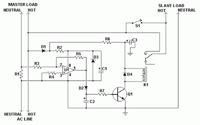
Parts
| C1, C3 | 2 | 10uF 35V Electrolytic Capacitor | |
| C2 | 1 | 1uF 35V Electrolytic Capacitor | |
| R1 | 1 | 0.1 Ohm 10W Resistor | |
| R2 | 1 | 27K 1/2W Resistor | |
| R3, R4 | 1 | 1K 1/4W Resistor | |
| R5 | 1 | 470K 1/4W Resistor | |
| R6 | 1 | 4.7K 1/2W Resistor | |
| R7 | 1 | 10K 1/4W Resistor | |
| D1, D2, D4 | 3 | 1N4004 Rectifier Diode | |
| D3 | 1 | 1N4744 15V 1 Watt Zener Diode | |
| U1 | 1 | LM358N Dual Op Amp IC | |
| Q1 | 1 | 2N3904 NPN Transistor | |
| K1 | 1 | Relay, 12VDC Coil, 120VAC 10A Contacts | |
| S1 | 1 | SPST Switch 120AVC, 10A | |
| MISC | 1 | Board, Wire, Socket For U1, Case, Mains Plug, Socket |
Notes
- This schema is designed for 120V operation. For 240V operation, resistors R2 and R6 will need to be changed.
- A maximum of 5A can be used as the master unless the wattage of R1 is increased S1 provides a manual bypass switch.
- THis schema is not isolated from the mains supply. Because of this, you must exercise extreme caution when working around the schema if it is plugged in.
Saturday, August 9, 2014
9V Automatic Battery NiCd Charger
This automatic NiCd charger for 9V NiCd batteries is using 555 timer properties and is very easy to build. Why is an automatic 9 volts NiCd battery charger? Because you can leave the battery for charging as much as you like: it will be always completely charged and ready for use when is needed. It wont be overcharged and it will not discharge.
9V Automatic Battery NiCd Charger Circuit Diagram :

With the values presented in the schema diagram, the battery charger NiCd schema is suitable for 6V and 9V batteries. 9 volt types with 6 and 7 cells are charging with 20mA; P1 must be adjusted so that the NiCd charger disconnects after 14 hours. Window inferior level is set at 1V below this value with P2.
5V battery type with 4 or 5 cells are charged at 55mA. Again, with P1 adjust the NiCd charger schema so it disconnects after 14 hours. Window inferior level must be set at 0.8V below this value.
Subscribe to:
Posts (Atom)
