Showing posts with label Box. Show all posts
Showing posts with label Box. Show all posts
Thursday, November 6, 2014
Junk box Fan Speed Controller
My new home theatre receiver was getting rather hot in the close confines of its cabinet, with the temperature reaching over 40°C after only about 30 minutes of use. To help lower the temperature, I decided to install a fan in the cabinet. A 75mm hole was cut in the shelf under the receiver, and a 12V fan salvaged from an old computer power supply was mounted underneath. The fan was powered from a 12V DC plugpack.
This did the job, keeping the temperature below 30°C even after prolonged use on a warm day. However, the fan was annoyingly loud when running at full speed. To reduce the noise level substantially, I built this fan speed controller with temperature feedback. The circuit was culled from variety of ideas found on various sites on the internet, with the final circuit designed from what was in the "junk box". Air temperature in the cabinet is sensed via an LM335 (TS1).
Circuit diagram:

Junk-box Fan Speed Controller Circuit Diagram
It is glued to a piece of aluminium about 25mm square with instant glue, which is then attached to the top of the receiver with "Blue-Tack". About 300mm of audio coax makes the connection back to the circuit board. The LM335’s output rises 10mV per degree Centigrade. It is calibrated to zero output at -273°C, so at 20°C, the output will be 2.93V. This is applied to the non-inverting input of a 741 op amp (IC1). A 1N4733 5.1V Zener diode provides a voltage reference for the inverting input via trimpot VR1. The output of the op amp drives a TIP122 Darlington transistor (Q1), which in turn drives the fan motor. The op amp gain was calculated to give about 12V to the fan at 40°C.
To keep the transistor cool, it is mounted on the metal base of a small plastic box, which is also used to house the components. Initial setup should be performed with everything turned off and the ambient temperature at about 20°C. Adjust the 10-turn pot until the fan just stops running. I used a gasket made from foam strips and "blue-tacked" them between the feet of the receiver to direct all of the airflow through it. The temperature now remains at about 32°C, the fan runs very quietly and continues to run down for about 30 minutes after the receiver is switched off.

Sunday, September 21, 2014
Explanation Fuse Box Chevrolet Suburban 89 Diagram
Fuse Box Chevrolet Suburban 89 Diagram - This show you about Fuse Box Chevrolet Suburban 89 Diagram.
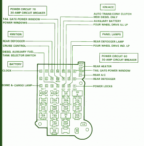
Fuse Panel Layout Diagram Parts: tailgate, power window, rear defogger, cruise control, diesel auxiliary fuel, tank selector switch, clock, cargo lamp, auto trans, auxiliary battery, rear defogger, rear heater, power locks.
Read More..
Fuse Box Chevrolet Suburban 89 Diagram
Fuse Panel Layout Diagram Parts: tailgate, power window, rear defogger, cruise control, diesel auxiliary fuel, tank selector switch, clock, cargo lamp, auto trans, auxiliary battery, rear defogger, rear heater, power locks.
Saturday, September 20, 2014
Mercedes Explanation Fuse Box Year Benz 1997 1998 F150 Diagram
Fuse Box Mercedes Benz 1997 & 1998 F150 Diagram - Below is Fuse Box Mercedes Benz 1997 & 1998 F150 Diagram.

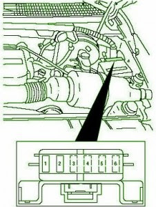
Fuse Panel Layout Diagram Parts: powetrain control module, trailer tow stop/turn lamps.
Read More..
Fuse Box Mercedes Benz 1997 & 1998 F150 Diagram
Fuse Panel Layout Diagram Parts: powetrain control module, trailer tow stop/turn lamps.
Friday, September 19, 2014
Mercedes Explanation Fuse Box Year Benz 1990 300 Diagram
Fuse Box Mercedes Benz 1990 300 Diagram - Below is Fuse Box Mercedes Benz 1990 300 Diagram.
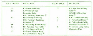

Fuse Panel Layout Diagram Parts: power seat relay, auxiliary fan, resistor relay, headlamp, washer, air injection, power window, convenience relay, seat belt warning relay, gear start relay, combination relay, power seat diode, parking brake, exterior lamp.
Read More..
Fuse Box Mercedes Benz 1990 300 Diagram
Fuse Panel Layout Diagram Parts: power seat relay, auxiliary fan, resistor relay, headlamp, washer, air injection, power window, convenience relay, seat belt warning relay, gear start relay, combination relay, power seat diode, parking brake, exterior lamp.
Fuse Box Ford 1999 Ranger XLT 2 5 lit Diagram
Fuse Box Ford 1999 Ranger XLT 2.5 lit Diagram - Here are new post for Fuse Box Ford 1999 Ranger XLT 2.5 lit Diagram.

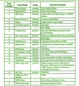
Fuse Panel Layout Diagram Parts: PCM power, horn, parking lamp, headlamp, PCM, low fluid resistor, RABS diode, PCM power diode, power window, ignition, I/P fuse panel, blower motor, ABS pump, A/C clutch system, 4wheel drive, fog lamp, ABS module.
Read More..
Fuse Box Ford 1999 Ranger XLT 2.5 lit Diagram


Fuse Panel Layout Diagram Parts: PCM power, horn, parking lamp, headlamp, PCM, low fluid resistor, RABS diode, PCM power diode, power window, ignition, I/P fuse panel, blower motor, ABS pump, A/C clutch system, 4wheel drive, fog lamp, ABS module.
Wednesday, September 17, 2014
Fuse Box BMW E36 Diagram
Fuse Box BMW E36 Diagram - Here are new post for Fuse Box BMW E36 Diagram.
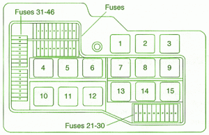

Fuse Panel Layout Diagram Parts: Taillight/Foglight Relay, System (main) Relay, Fuel Pump Relay, Oxygen Sensor Heater Relay, Emergency Flasher Relay, Horn Relay, High Beam Relay.
Read More..
Fuse Box BMW E36 Diagram
Fuse Panel Layout Diagram Parts: Taillight/Foglight Relay, System (main) Relay, Fuel Pump Relay, Oxygen Sensor Heater Relay, Emergency Flasher Relay, Horn Relay, High Beam Relay.
Fuse Box Ford 66 Montego Diagram
Fuse Box Ford 66 Montego Diagram - Here are new post for Fuse Box Ford 66 Montego Diagram.
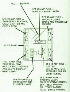
Fuse Panel Layout Diagram Parts: terminal, fuse emergency flasher, cigar lighter, clock feed, fuse panel, fuse courtesy, dome, cargo, luggage, glove compartment lamp, instrument panel, cluster lamps, .fuse heater, warning lamps, seat belt warning, brake warning, brake warning, air conditioning, windshield washer, accessory feed.
Read More..
Fuse Box Ford 66 Montego Diagram


Fuse Panel Layout Diagram Parts: terminal, fuse emergency flasher, cigar lighter, clock feed, fuse panel, fuse courtesy, dome, cargo, luggage, glove compartment lamp, instrument panel, cluster lamps, .fuse heater, warning lamps, seat belt warning, brake warning, brake warning, air conditioning, windshield washer, accessory feed.
Tuesday, September 16, 2014
Fuse Box Ford 2010 Fusion Power Distribution Diagram
Fuse Box Ford 2010 Fusion Power Distribution Diagram - Here are new post for Fuse Box Ford 2010 Fusion Power Distribution Diagram.
![Fuse]()
![Fuse]()
Fuse Panel Layout Diagram Parts: power assist steering, powertrain control module, starter motor relay, anti lock brake system, wiper washer, ABS valve, transmission module, alternator, console power point, A/C clutch, cooling fan motor, fuel relay, passenger power point, driver power seat, fuel pump, one touch start, heated side mirrors, back up lamp, A/C clutch, Injector, generator powertrain component, ignition coil, blower motor relay, fuel relay, starter relay,PCM relay.
Read More..
Fuse Box Ford 2010 Fusion Power Distribution Diagram


Fuse Panel Layout Diagram Parts: power assist steering, powertrain control module, starter motor relay, anti lock brake system, wiper washer, ABS valve, transmission module, alternator, console power point, A/C clutch, cooling fan motor, fuel relay, passenger power point, driver power seat, fuel pump, one touch start, heated side mirrors, back up lamp, A/C clutch, Injector, generator powertrain component, ignition coil, blower motor relay, fuel relay, starter relay,PCM relay.
Monday, September 15, 2014
Explanation Fuse Box Chevrolet Tracker 2001 Diagram
Fuse Box Chevrolet Tracker 2001 Diagram - This show you about Fuse Box Chevrolet Tracker 2001 Diagram.
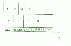

Fuse Panel Layout Diagram Parts: accessory power ooutlet, electronic fuel injecion system, headlamp, high beam indicator, heater, hazard lamp, rear combination lamp, dome light, horn, cigar lighter, radio, ignition coil, meter, wiper, washer, rear defroster, turn signal, back up lamp, anti lock brake system, all electrical loads, air conditioning.
Read More..
Fuse Box Chevrolet Tracker 2001 Diagram
Fuse Panel Layout Diagram Parts: accessory power ooutlet, electronic fuel injecion system, headlamp, high beam indicator, heater, hazard lamp, rear combination lamp, dome light, horn, cigar lighter, radio, ignition coil, meter, wiper, washer, rear defroster, turn signal, back up lamp, anti lock brake system, all electrical loads, air conditioning.
Sunday, September 14, 2014
Mercedes Explanation Fuse Box Year Benz 2001 SLK 320 Diagram
Fuse Box Mercedes-Benz 2001 SLK 320 Diagram - Below is Fuse Box Mercedes-Benz 2001 SLK 320 Diagram.


Fuse Panel Layout Diagram Parts: maxi fuse block, front of vehicle, fuse block (A, B, C)
Read More..
Fuse Box Mercedes-Benz 2001 SLK 320 Diagram
Fuse Panel Layout Diagram Parts: maxi fuse block, front of vehicle, fuse block (A, B, C)
Subscribe to:
Posts (Atom)
