Friday, December 12, 2014

Broadcast Transmitter Circuit Diagram

transmitter-schematic


In this circuit, a 74HC14 hex Schmitt trigger inverter is used as a square wave oscillator to drive a small signal transistor in a class C amplifier configuration.The oscillator frequency can be either fixed by a crystal or made adjustable (VFO) with a capacitor/resistor combination.
Read More..

Intercom Circuit with Transistors

intercom-diy-project

This is a 2-station simple intercom circuit build based on transistors part and using common 8R mini speakers. The speaker works as microphone and generate sound, so there is no need microphone for this intercom. The "press-to-talk" switches should have a spring-return so the intercom can never be left ON, push on switch can be used for this kind of task. 
Read More..

Voltage inverter circuit


This voltage inverter circuit powering a dual supply op amp from a single battery problem. The circuit simply takes a positive voltage and inverts it. It uses only one 555 timer and a few other passive components, so it doesn't add much in the way of size and cost to a project. 
Read More..

Thursday, December 11, 2014

Voltage Inverter Circuit


This simple and inexpensive circuit can produce a dual (positive and negative) voltage from a single supply input.
It is therefore extremely useful for powering opamp and other circuits that require a dual voltage from a single battery.
Read More..

Thursday, November 20, 2014

555 basic PWM controller

IC Timer 555 has a basic PWM controller with features pengendalianlebar 0 .. 100% pulse that is controlled using the R1, at the time of controlling the oscillator frequency relatively stabi so it may be used to build the Simple PWM controller. Frequency of Simple PWM controller 555 depending on the value of R1 and C1, values ​​shown R1 and C1 will form the output with a frequency of 170 to 200 Hz. Diode-diode used in the Simple PWM controller With this 555 can use a 1N4148.

555


R2, R3 and C3 form a giver triger circuit beginning at the reset IC 555 for 2 seconds. If you want to use a series of Simple PWM controller 555 with the V + not +12 V, it does not matter to raise tilapia R2 where (V + * R2) / (R2 + R3) is about 2, because it limits the signal level reset is 0.5 .. 1V. If you do not do that, then signal the kickstart to get too close to the limit reset signal reception.

Q output of 555 on the Simple PWM controller circuit 555 is used for driver PWM pulse, so that the discharge pin is used for transistor output driver instead. This is an open collector output, and is used as an active signal is low, so it can work. D3 protects the output transistor of the load induction. You may replace any suitable transistors for Q1, BD140 is 1.5 amps.

C4 and C5 is the power decoupling capacitor for the IC 555 on the Simple PWM controller circuit 555, which produce relatively large level of push-pull output stage.
Read More..

20W Car Audio Amplifier with LM1875

This is just addition 20W audio amplifier circuit , but this time based on the LM1875 audio amplifier IC from National Semiconductors. With a 25V bifold ability accumulation LM1875 can bear 20W of audio ability into a 4 ohm speaker. The LM1875 requires actual beneath external components and has actual low distortion.

The IC is aswell arranged with a lot acceptable appearance like fast bulk rate, advanced accumulation voltage range, top achievement current, top achievement voltage swing, thermal aegis etc. The IC is accessible in TO-220 artificial ability amalgamation and is able-bodied acceptable for a array of applications like audio systems, servo amplifiers, home theatre systems etc.

Notes.

  • Assemble the circuit on a good quality PCB.
  • Use +/-25V DC dual supply for powering the circuit.
  • K1 can be 4 ohm, 20W speaker.
  • A proper heat sink is necessary for the IC.
  • F1 and F2 are 2A
Read More..

Tone Control Circuit

3 Band Tone Control circuit uses an op-amp as an amplifier end. Tone Control circuit is a regulator of tone bass, midrange and treble or 3 band called because it can set the three tones. Filter circuit is applied to the series of "Tone Control 3 band" This type baxandal like the title of this article. 

Results filtering regulator tone or tone control baxandal type is good, because there is no signal level is wasted directly into the ground. Range frequency tones generated from Tone Control 3 band was determined by the configuration of the R and C of the filter section baxandal. As an amplifier on Tone Control The set of three band use traditional IC LF351 has slewrate high and high input impedance. For more details, series 3 Band Tone Control as follows.


Figure Series 3 Band Tone Control


3


3 Band Tone Control circuit above using LF351 Op-Amp is used to strengthen the signal after filtering by the filter process baxandal. Level tone Bass, Midrange and Treble settings are determined by potensio R1, R2 and R3. Frequency filter in the circuit above baxandal to 50 Hz bass tone, tone Midrange 1 KHz and 10 KHz for Treble tone.
Read More..

Wednesday, November 19, 2014

1000Watt Audio Power Amplifier Blazer Circuit

1000Watt Audio Power Amplifier Blazer Circuit

This is a audio power amplifier Blazer circuit provides up to 1000Watt . This fascinating routes several sensible bass and treble alive. Importantly ought to opt for Power offer supply, that has been fairly high voltage category 70Vdc GND -70V 10A is that the current low level.

The transistors are 2SC3858 (NPN) and 2SA1494 (PNP), and have high bandwidth, wonderful safe operating space, high linearity and high gain. Driver transistors are 2SC5200 (NPN) and 2SA1943 (PNP). All devices are rated at 230V, with the facility transistors having a 150W dissipation and also the drivers are 50W.

This circuit describes an amplifier, power offer and tests procedures that are all inherently dangerous. Nothing described during this article ought to even be thought-about unless youre totally experienced, grasp specifically what youre doing, and are willing to require full 100% responsibility for what you are doing. There are aspects of the look which will need analysis, fault-finding and/or modification.
Read More..

Filter freq dirty from an fm transmitter

Low pass filter is a circuit to filter freq dirty from an fm transmitter. so we get a clean signal. and can maximize the output power generated from the booster. low pass filter is capable to 150 watts. in this post . file [lay] that can only be opened with software sprint layout. for those interested please download here.


Read More..

Circuits Schematic Mono Audio Mixer

CircuitsCircuits Schematic Mono Audio Mixer

This mixer shows you how to accomplish microphone pre-amps for low and hi impedance mics. Use the everyman babble op-amp you can acquisition that has agnate characteristics to the LT1112 (although it is not too bare itself). The lath has added band inputs and follows the schematic.
Read More..

Tuesday, November 18, 2014

FM Moulator with IC 555

FM Modulator circuit is a simple FM modulation circuit using IC 555, where the resulting modulated signal has a tenuous meeting depends on the signal frequency information. 

FM

FM

The resulting signal can be spelled out quite nice and stable so that the result will be more perfect. No winding or inductor in series modulator, so you do not need to bother to make a winding and calculate the value of the coil that you created it. With this circuit the desired value of frequency modulation can be obtained easily by calculating the frequency of IC 555 in general, which is determined by the resistor 6.8 K and 3.3 K and 0.1 UF capacitor. To obtain the other frequencies of your stay replace one or all three components.

Actually fm modulator ic 555 circuit is very simple though, but I think it reliable enough to handle a simple application purposes that do not require a big power or a very high frequency. But if you want more power you can add the RF amplifier circuit at the output of this circuit. Thus, the results of modulated signal can be amplified with the help of a series of supporters. In accordance with my experimental series modulators can work well at frequencies below the MHz range, because it is not IC IC 555 which is devoted to support of a very high frequency. You can use oscilltor transistor circuit, XTAL or others if you need a very high frequency.

The difference circuit with IC 555 on the multivibrator circuit in general is the use of pin 5, on the FM Modulator circuit is pin 5 of IC 555 is used as input information signal, which in turn will influence the shape of the output signal (modulated). But in applying this 5 pin multivibrator functions normally associated with 0.01 UF capacitor or left alone.
Read More..

USB cable signals

USB cable consists of 4 wires plus a conductor wire wrapping, such as the protectors are usually found in the audio cable. Cable number 1 is used to channel resources to the voltage of 5 volts, if necessary USB devices may draw power from this line and should not exceed 100 mA. Computer equipped with USB capability, is required to provide power at 100 mA for this purpose. USB devices that require more power than the aforementioned provisions, must provide their own resources for the purposes work equipment.


The USB cable signals

Number 4 is the ground cable as a back channel source voltage of 5 volts. Cable number 2 and number 3 is used for signal transmission. No. 2 cable and cable called D-3 numbers called D, the voltage on the two channels is changed between 0 Volt and 3.3 Volt. Digital signal is sent through the two channels are said to be difference signal, which means that the signal digital 0 or 1 is not declared to the magnitude of the voltage on the channel to the ground, as well as digital signals used in the IC TTL (transistor Transitor Logic) or the RS232 channel.

Digital signal is expressed by the voltage difference between the two cables. If the voltage on the D channel is higher than the voltage at D-channel, then the information transmitted digital signal is 1 , otherwise the digital signal 0 is expressed by the voltage at D

At low speed USB devices, the D-channel to 3.3 Volt dipasangan custody, or in the absence of information transmission, the channel is in state 0 . For full speed USB device, such resistance is connected to the D channel, so that in the absence of data transmission channels are in state 1 .
Read More..

Anti Log Converter Schematic Circuits

Anti-LogAnti-Log Converter Schematic Circuits

Anti-log or exponential bearing is artlessly a amount of rearranging the logarithmic circuitry. The ambit diagram beneath shows the chip of the log adapted to accomplish an exponential achievement from a beeline input.

The emitter of Q2 in admeasurement to the ascribe voltage is apprenticed by amplifier A1 in affiliation with transistor Q1. The beneficiary accepted of Q2 varies exponentially with the emitter-base voltage.

Read More..

Analog Versatile Circuit MIC 640 Acquisition System

This tour, available in Stainless DIL 8 legs, can measure 4 analog voltage independent between 0 and 5 volts, and send the result of this measure in the form of four characters on a standard asynchronous serial link. Its serial output is directly TTL or CMOS compatible and can be connected to a serial input RS 232 by simply adding a resistor.

The MIC 640 can operate in automatic mode, thus sending the result of four steps every second, or in command mode, in which case it sends the result of four measures under the control of external logic signal. In this latter method that we use here.

Its consumption is extremely low, it is possible to feed signals from the unused serial port RS 232, subject of course not to waste the little energy available in external circuits involved too greedy.

This circuit, easily available in France, costs less than 18 euro which makes it an ideal candidate for this achievement we will find the schema without tarder.Si you want more information about the MIC 640;s complete data sheet entirely in French, is available for download by clicking this link.

Schematic acquisition module

AnalogAnalog Versatile Circuit MIC 640 Acquisition System

The heart of the module is obviously the MIC 640, spotted IC1 on the figure below. It is directly connected to the serial input RS 232 PC via limiting resistor R1 current.

His entry called CTRL to define its mode of operation. Left to the body, it makes it automatically perform a conversion on each input per second, whereas if it is reduced to levels as high as in this case, it triggers a conversion of each entry at each grounding.

These earthed take place through the transistor Q1 controlled by the serial data output TXD of RS 232, via the diode D4. This same output is through the diode D3 and this time the capacitor C3, to produce the negative supply voltage of the input stage that we discover in a moment.

The control lines DTR and RTS serial interface they provide for the positive supply via diodes D1 and D2. This voltage is unregulated, is the positive power of the input stage. By cons, it is regulated to 5 volts through IC2 so that it feeds a voltage very stable MIC 640.

As the current and available for both the positive supply for the negative supply is still low (10 mA max), I had to carefully choose the components used and they will not be replaced under any pretext. IC2 is indeed a regulator 5 volts 3 feet very low: in one case in 2936 SM Z5 which absorbs only 500 uA. For information, its "equivalent" the 78L05 consumes 3 mA in the same situation!

The input stage meanwhile was achieved using four operational amplifiers effect transistor field-mounted voltage followers. This confers to the module input impedance greater than 100 MW. All four amplifiers are combined in one box, referenced LF 444 at National Semiconductor, whose total consumption does not exceed 800 uA for the four amplifiers! Again, no question of putting such a TL 084 which face voracious with its 5.6 mA!

This input stage is protected from excessive voltages through resistors R7 to R10 and diodes D6 to D13. If you precede the various stages of converting physical quantities / voltage, you can possibly do without protection diodes that degrade somewhat the very high input impedance of 444 MQ due to their leakage current. It is in fact only 50 pA maximum input of 444 LF while a diode, even small leaks, easily misses 1 nA or 20 times more!
Read More..

Monday, November 17, 2014

L297 Stepper Motor Controller Circuits

L297L297 Stepper Motor Controller Circuits

Four appearance drive signals for two appearance bipolar and four appearance unipolar footfall motors in microcomputer-controlled appliance is calmly implemented application L29 Stepper Motor Controller IC. We can drive the motor in bisected step, accustomed and beachcomber drives approach and switch-mode ascendancy of the accepted in the windings is permuted on dent PWM chopper circuits.

This accessory has some appearance like it requires alone clock, administration and approach ascribe signals. Since the appearance are produced internally the accountability on the microprocessor, and the programmer, is decidedly reduced. This accessory is army in DIP20 and SO20 packages. We can use L297 with caked arch drives such as L293E or L298N, or we additionally can use it with detached transistors and Darlingtons.
Read More..

High Power Audio Amplifier 2800W

Mono high power amplifier is actually a powerful 1400 W, but if this hihgh power amplifier circuit is doubled and you want to create stereo, high power amplifier the necessary components and pcb requires two-fold. So if the stereo high power amplifier 2 X 1400W. Schematic Circuit diagram is still less by looking at the circuit that was so below, the finished circuit has been added with a gains using JRC4558 IC by the two and the picture ic where it can be seen below. For circuit buffers, drivers, and booster use multiple transistors and other components (can be seen listed component). And high power amplifier project that is so below is just part of the buffer and driver while the booster has not been made​​. For additional transistors in the booster or high power amplifier end scheme can be found Booster output power amplifier.

Click schematic to view larger
Part List :

Resistor
R1_____560Ω
R2_____100Ω
R3_____2K2Ω
R4_____560Ω
R5_____1Ω
R6_____27KΩ
R7_____10KΩ
R8_____100Ω
R9_____100Ω
R10____100Ω
R11____12KΩ
R12____100Ω
R13____100Ω
R14____100Ω
R15____27KΩ
R16____2K2Ω
R17____560Ω
R18____100Ω
R19____10KΩ
R20____330Ω
R21____47Ω 2W
R22____56Ω
R23____2K2Ω
R24____22Ω
R25____56Ω
R26____180Ω
R27____500-1KΩ Trim
R28____560Ω
R29____56Ω
R30____56Ω
R31____22Ω 1W
R32____5Ω6 2W
R33____10Ω
R34____180Ω
R35____100Ω
R36____22Ω 2W
R37____180Ω
R38____56Ω
R39____47Ω 2W
R40____5Ω6 2W
R41____10Ω
R42____10Ω
R43____10Ω
R45____10Ω
R46____0.22Ω 5W
R47____0.22Ω 5W
R48____0.22Ω 5W
R49____0.22Ω 5W
R50____10Ω 5W

Capacitor
C1_____1цF
C2_____1.5nF
C3_____0.1цF 250-275V
C4_____0.1цF 250-275VC5_____100nF
C6_____100цF 50V
C7_____39pF
C8_____330pF
C9_____330pF
C10____330pF
C11____47nF 250-275V
C12____220nF 250-275V

Transistor
T1_____MJE340
T2_____2N5551 / C2240
T3_____2N5551 / C2240
T4_____2N5551 / C2240
T5_____2N5551 / C2240
T6_____2N5401 / BF423
T7_____2N5401 / BF423
T8_____2N5401 / BF423
T9_____2N5401 / BF423
T10____MJE350
T11____B1186
T12____TIP127
T13____D1763
T14____D1763
T15____B1186
T16____C5198
T17____A1941
T18____2SC2922 / MJ15024G
T19____2SC2922 / MJ15024G
T20____2SA1216 / MJ15025G
T21____2SA1216 / MJ15025G
This installation include gain JRC4558

This is pcb design

Installation with booster
PCB design by SIGMA-4 Madiun ©

Other high power amplifier circuit : 1500W HiFi Power Amplfier
Read More..

Loading coil antena telex 88 108mhz

This post is for an antenna loading coil telex broadcast on freq. let us buy Simply put wrote specifically for the antenna loading coil at the store component telex, because loading the settings is still for freq 2 meter, we must slightly modify it. The trick is easy, just replace the existing loops. original about 5 convolution convolution continues we replace 10 with 1 to 1.5 mm diameter wire. for more details see the pictures. may be useful ..


Read More..

Sunday, November 16, 2014

TDA2006 12W Audio Amplifier Circuit

This 12w amplifier circuit is build round the TDA2006 integrated circuit who options a brief circuit protection system, and a thermal shutdown system in case of overheating. With a 12v power supply the circuit delivers 12w on a 4 ohm speaker and 8w on a 8 ohm speaker. The integrated circuit will work with a power supplyr between 6v and 15v max.

The TDA2006 is monolithic integrated circuit in package, {supposed to be used as a low frequency category "AB" amplifier. At ±12V, d = 10 and frequently it provides 12W output power on a 4Ω load and 8W on a 8Ω . The TDA2006 provides high output current and has terribly low harmonic and cross-over distortion. any the device incorporates an inspired (and patented) short circuit protection system comprising a rendezvous for automatically limiting the dissipated power therefore on keep the operating urpose of the output transistors at intervals their safe operating space. a standard thermal shutdown system is additionally included. The TDA2006 is pin to pin equivalent to the TDA2030
Read More..

MCS51 AT89S51 microcontroller architecture

Microcontroller architecture we need to know if we will use this MCS51 microcontroller in a control MCS51 microcontroller-based electronic devices. AT89S51 microcontroller MCS51 architecture actually almost similar to the other MCS51. MCS51 Microcontroller AT89S51 is MCS51 family of microcontrollers with 40 pins. In this article MCS51 AT89S51 microcontroller architecture can be seen, although not all.
AT89S51 microcontroller has several features, among others, as follows:

4 K bytes Flash PEROM
The frequency of 4 Hz - 24 MHz
128 x 8 bit Internal RAM
32 channels of I / O bi-directional
2 pieces of 16-bit timer
2 external interrupt and internal interrupt 3
A pair of serial communication ports
Here is a brief description of each leg functions contained in the microcontroller AT89S51.

GND (Ground) or grounding function as a negative supply or ground path.
VCC serves to route the positive power supply 5V DC to the microcontroller.
RST / Vpp is a microcontroller reset line with the transition low to high, Vpp is used as supply voltage when programming the microcontroller.
ALE / PROG, this foot is used to capture or to a low address latch (A0.. A7) to the external memory during normal operation. Receive a program pulse input during the programming of internal Flash PEROM.
PSEN Program Store Enable is the PSEN output is where the control signal or activate a program that allows an external memory (EPROM external) to the data bus during normal operation.
EA / Vpp (External Access Enable) is to direct the selection of program execution from external memory or internal memory and then starts a new external memory. Legs are also receive 12.75 V for Flash programming power supply PEROM.
XTAL1 is the input path to the amplifier oscillator on a microcontroller or external input source pulse from the microcontroller.
XTAL2 is the output path of the oscillator amplifier.
P0.1 - P0.7 is an output port / input (I / O) type bidirectional open-drain (without internal pullup). Port 0 can be configured as a bus address / data, the low (low byte) during the process of accessing the data memory and external programs.
P1.0 - P1.7 is I / O ports are equipped with two-way internal pullup. Port 1 also receives the address low during programming and verification of flash PEROM.
P2.0 - P2.7 is I / O ports equipped with two-way internal pullup. Port 2 is the high part of byte address (high byte) for taking instructions from external program memory and during programming and verification of flash PEROM.
P3.0 - P3.7 is I / O ports equipped with two-way internal pullup. Port 3 has alternative functions, including receiving the control signals along with the port 2 during programming and verification of flash PEROM.
Microcontroller AT89S51 has a data memory address space and a separate program. The separation of program memory and data memory allowing the data accessed by an 8-bit addresses, allowing you to quickly and easily stored and manipulated by an 8-bit CPU. Internal memory location 0000H to the program occupies 0FFFh, while for external memory location 1000H to occupy FFFFH. Data memory occupies a separate address space from Program Memory.
Read More..

Saturday, November 15, 2014

2×5 W STEREO POWER AMPLIFIER CIRCUIT BASED ON BA5417

BA5417 Stereo Power Amplifier

BA5417 is a stereo amplifier IC with a lot of good features like thermal shut down, standby function, soft clipping, wide operating voltage range etc. The IC can deliver 5W per channel into 4 ohm loud speakers at 12V DC supply voltage. The BA5417 has excellent sound quality and low THD (total harmonic distortion) around 0.1% at F=1kHz; Pout=0.5W.

Description

Setup and working of this stereo power amplifier circuit is somewhat similar to the BA5406 based stereo amplifier circuit published previously. C10 and C11 are DC decoupling capacitors which block any DC level present in the input signals. C2 and C6 couples the amplifiers left and right power outputs to the corresponding loud speakers. C1 and C5 are bootstrap capacitors. Bootstrapping is a method in which a portion of the amplifiers is taken and applied to the input. The prime objective of bootstrapping is to improve the input impedance. Networks R1,C3 and R2,C7 are meant for improving the high frequency stability of the circuit. C4 is the power supply filter capacitor. S1 is the standby switch. C8 is a filter capacitor. R3 and R4 sets the gain of the left and right channels of the amplifier in conjunction with the 39K internal feedback resistors.


Circuit Diagram


Notes

  • Supply voltage range of BA5417 is from 6 to 15V DC.
  • The recommended supply voltage for this circuit is 12V DC.
  • The power supply must be well regulated and filtered.
  • BA5417 requires a heatsink.
  • The circuit can be assembled on a perf board without much degradation in performance.
Read More..

Friday, November 14, 2014

METAL DETECTOR CIRCUIT

The device we then build will function as a metal detector that can scout out metal objects, such as coins, nails, keys such as car keys you may not be able to find, and even gold if youre looking for in a beach (though this one may not have industrial strength). This metal detector can detect certain kinds of metal- especially iron-containing metals, which are called ferrous metals, even if under a half-inch of drywall or sand.

How this metal detector works is that it uses an IC that generates an AC signal that goes through a coil. Metal objects are objects which conduct electricity, so a current can be induced in these metal objects. When the coil in the metal detector comes near a metal object, the electromagnetic field in the coil induces currents in the metal object. The electromagnetic field generated by the metal changes the current in the coil. When the signal changes, the IC turns on an LED i.e. alerting the user to the presence of a metal.

Circuit Diagram

Metal Detector Circuit
Parts Needed
  • TDA0161 Proximity Detector (IC1)
  • 2 1KΩ Resistors (R1, R4)
  • 10KΩ Potentiometer (R2)
  • 330Ω Resistor (R3)
  • 120Ω Resistor (R5)
  • 2N3904 Transistor (Q1)
  • 2 4.7nF ceramic capacitors (C1, C2)
  • 680 picohenry bobbin-type Inductor
  • Battery Holder for 4 AA batteries (6V)
  • LED
  • SPST Switch

Explanation of Circuit

Inductor L1 : The inductor L1 forms a parallel circuit with the capacitor C1 to form an LC parallel circuit. When a signal that oscillates at several KHz passes through this circuit, the signal creates an electric field around the coil. When you bring the coil near a metallic object, that electric field induces an oscillating signal in the object. So when the oscillating signal has been induced in the metallic object, the signal in the object creates an electric field that induces current in the coil. This current changes the oscillating signal running through the LC parallel circuit.

TDA0161 Proximity Detector IC : This IC is a proximity detector. This IC suplies the oscillating signal that is sent through the LC parallel circuit. The IC also responds to any changes in the signal. The IC has an output of 1 milliamperes (mA) or less if the coil is far from a metallic object and an output of 0mA or higher if the coil is near a metallic object. 
Thus, this IC is at the heart of this circuit. When the object is far from a metallic object, the current which the IC produces is insufficient to drive the LED. Thus, the LED does not turn on. When the coil is near a metallic object, the IC produces sufficient power to drive the LED and it turns on. 

Resistor R1 and Potentiometer R2 : These resistors are used to calibrate the TDA0161 IC to the LC circuit. You calibrate it by adjusting the potentiometer to change the current output it creates in accordance with the proximity of metal to the coil. You can adjust so that it can detect metals at the distances which you want it to. By increasing the potentiometer resistance, the IC will create less current output. Therefore, a metal must be placed closer to the coil in order for the LED to light. By decreasing the potentiometer resistance, the IC produces less current output, so the metal doesnt have to be placed as close to the coil. Its up to you to set the adjustment.

2N3904 Transistor (Q1) : The 2N3904 transistor provides amplification, so that there is sufficient current to power the LED. Without this transistor, there would not be enough power to turn on the LED. 

LED : The LED in the circuit serves as an indicator to when there is a presence of a metal. When a metal is in close proximity to our electronic circuitry, the LED turns on. This shows we have found metal. When the LED is off (not lit), then our metal detector has not detected metal and indicates no metal is in close proximity.

6 volts : The 6 volts is the supply power to the entire circuit. This 6 volts is supplied through 4 AA batteries in series. Being that each battery supplies 1.5 volts, 4 AA batteries (1.5V * 4) provides 6V. This 6 volts gives power to every component in the circuit.

SPST Switch : The SPST switch allows us to shut off power to the circuit, if we want the metal detector power shut off, just like any electronic device would have. This just serves asn an on/off switch.

This circuit detects metal through the coil, L1. Once metal is placed near the inductor L1, it will trigger current production from the proximity detector IC, which in turn lights the LED. So to test this circuit, just place a metallic object near this inductor. When done, the LED should turn on. When the metallic object is moved away, the LED should shut off. 
Read More..

Thursday, November 13, 2014

Borg Warner Truck Wiring Diagram

The following truck wiring diagram is originally scanned from 1965 Chilton’s manual. Should you have an all original truck with overdrive, this diagram should be usable. This manual contains a diagram for wiring a split control setup for your T-85N transmission. This can be used for one you’ve bought outright and have no original circuit for, or modifying the one you already have. The DPDT relay is Double Pole Double Throw relay.

Find more detail information about Borg Warner Truck Wiring Diagram in the following article. (source: hydratech.com)

Read More..

Pulse Generator And Signal Tracer

Dual-purpose test-instrument, Very simple circuitry, 1.5V Battery-operated
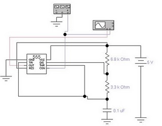
This simple circuit generates narrow pulses at about 700-800Hz frequency. The pulses, containing harmonics up to the MHz region, can be injected into audio or radio-frequency stages of amplifiers, receivers and the like for testing purposes. A high-pitched tone can be heard from the speaker of the device under test when all is working properly. The clip must be connected to the ground of the device under test, touching with the probe the different stages of the circuit, starting from the last stage and going up towards the first. When the tone is no longer heard, the defective stage has been found.

Connecting an earclip or headphone to J1, the circuit will automatically change into a two-stage amplifier and any audio signal coming from the device under test and picked-up by the probe will be heard through the headphones. The testing of a circuit should be made in the reverse manner, i.e. starting from the first stage and going down until the last stage. When nothing is heard, the defective stage has been found.

Circuit diagram:
Pulse
Pulse Generator And Signal Tracer Circuit Diagram

Parts:
R1________________1M 1/4W Resistor
R2,R4_____________2K7 1/4W Resistors
R3________________150K 1/4W Resistor
C1________________2n2 630V Ceramic or Polyester Capacitor (See Notes)
C2,C3_____________4n7 63V Ceramic or Polyester Capacitors
D1_______________1N4148 75V 150mA Diode
Q1_______________BC547 45V 100mA NPN Transistor
Q2_______________BC557 45V 100mA PNP Transistor
SW1______________SPST miniature Slider Switch (See Notes)
J1_______________Stereo switched 3mm. Jack socket (See Notes)
Probe____________Metal Probe 3 to 5 cm. long
Clip______________Miniature Crocodile Clip
B1_______________1.5V Battery (AA or AAA cell etc.)Circuit operation:Q1 & Q2 form a complementary astable multivibrator, whose operating frequency is set mainly by R3, C2 & C3 values. Output pulses are taken at Q2 Collector and applied to the probe by means of decoupling capacitor C1. D1 provides a symmetrical shape for the output waveform. If an earclip or headphone jack is plugged into J1, the connection from Q2 Collector and C1 - C2 is broken by the switch incorporated into J1: in this case the circuit becomes a two-stage amplifier.Notes:
  • If you intend to use the circuit to test valve operated devices C1 must be a 630V type. Working with low voltage supply transistor devices the voltage of C1 can be lowered to 63 or 100V.
  • If instead of a short probe, you intend to connect the circuit to the device under test by means of a piece of wire longer than a few centimeters, a small ceramic capacitor (470 to 1000pF) should be added in parallel to D1 to prevent unwanted RF oscillation.
  • Current drawing when in Pulse-Generator mode is about 60µA and 1.2mA when in Signal-Tracer mode operation. Therefore SW1 can be omitted, provided that the earclip or headphones are unplugged when the circuit is unused.
  • J1 is a stereo switched jack socket wired to obtain a series connection of the two earpieces forming a stereo headphone. In this manner the circuit is loaded with a higher impedance and sensitivity will be improved.
  • Therefore, the higher the load impedance the more sensitive the Signal-Tracer. In any case, common 32 Ohm impedance mini-headphones suitable for walkman sets will work fine.
  • A crystal (high impedance) earpiece is a good solution, provided you substitute J1 with a mono switched jack socket.
  • The entire circuit can be easily fitted into a pen-like enclosure, with the probe protruding like a nib
Read More..

Cross Linking With Two Patch Cables

In networks, the supremacy of coax cable is a thing of the past. Nowadays, Ethernet connections are made using UTP cables. The BNC plug has yielded to the 8-way RJ45 plug. Previously, coax cables were daisy-chained from computer to computer and terminated at the two ends using 50-_ resistors, but modern networks use central ‘socket boxes’ (switches and/or hubs) to interconnect everything. The connections between the hubs and the computers are made using patch cables having the same sequence of leads in the RJ45 connectors at each end. For making a direct connection between two computers without using a hub or switch, a ‘crossover cable’ is used.Cross-Linking
Cross-Linking
Cross-Linking
Cross-LinkingSuch a cable has the leads cross-linked in order to allow the two computers to directly communicate with each other. If there are problems with the network, it can be handy to be able to directly interconnect twocomputers, or directly connect a computer to a cable or ADSL modem without using a hub or switch. A long crossover cable is not always available, and shoving around computers is not an attractive alternative. Consequently, we can use a dual RJ45 wall outlet box to construct an adapter, which can be used to interconnect the two patch cables coming from the equipment in question. This outlet box must be wired to create a cross-linked connection. This is done by making the following internal connections:
  • 1 → 3
  • 2 → 6
  • 3 → 1
  • 4 → 4
  • 5 → 5
  • 6 → 2
  • 7 → 7
  • 8 → 8
Read More..

Isobaric 4th order Bandpass Subwoofer Box Design

The fact that we need a subwoofer means that something is missing in the performance of the main speakers. This is not surprising, since the speakers unfortunately have to coexist with families, women and companions, leading to the inevitable Compact, stand-mounted speaker. Modern, compact speakers are excellent performances, but there is no further away from the laws of physics, small box = bad bass. So, modern speakers designed for a response in the low-limit?

User isobaric subwoofer on the Altec Lansing FX4021 and FX5051


4th isobaric subwoofer box design

The subwoofer is a bit of a word misnomer. It includes sub-audio course can not hear you. We mean really low sound. This does not mean we can not "collect" the sub-audio frequencies. The body can not perform under the form of audio-frequency vibrations and can strengthen the reality of the listening experience. There is usually little more low audio below 20Hz in most of the music.

The only (not electronic), an instrument can produce something in this Church is the body 16.67Hz. Even if this body is equipped with the solid pipe is usually filled with something to prevent the building collapsing around!

For practical reasons we can arrange to 20Hz as the lowest audio frequency that we want to reproduce, may be less than that, the boxes are often quite large. OK. So who determines the lowest frequency we want the subwoofer to handle, but what about the highest frequency?
It is easy to match the response of the existing speakers.

In my case, my speakers are-3dB at 47Hz. That is a lot better than most small speakers, 70-80Hz at-3dB is fairly typical. Ideally the subwoofer to be on the same-3dB frequency. It is easy acheivable a low-pass electronic filter. These can easily be made adjustable to fit almost all existing stakeholders.

Why only one subwoofer, we have two for stereo? The answer to this depends on how the human ear perceives direction. The brains very carefully compares the phase of sounds in the left ear or right and take a decision on this basis.

At high frequencies, the distance between the ears is an important part of the wavelength and the phase difference is large. Because the frequency is reduced, the distance between the ears small compared to the wavelength.

The phase difference is reduced making it difficult for the brains towards the sound calculates. It is not by any means the whole story, the ears also use the level difference and the slight head movements to better determine the direction. Below 200Hz, the human auditory system is almost fully able to determine direction, so it does not matter if the bass is in stereo, mono or even in the room where it originated.

Thus, a subwoofer is all you need. It is normal that the sum of the left and right channels within the subwoofer, so no information is lost. Joint Stereo is often used in the MP3 coding scheme. The low frequencies are encoded in mono, stereo at higher frequencies.

I have several cheap 180 mm / 6.5 "drives and carefully measured their parameters. This step is crucial in this kind of design that even small errors affect the frequency response drastically.

I used my speaker WinISD and added to the database to track the response and the size of the box to calculate. Compromises are necessary in this kind of design. You can find a good performance and a very narrow bandwidth or poor performance and a wider bandwidth. What is acheivable entirely dependent on the properties of the drive. I was fortunate in that my 3 pounds produced a pilot-3dB bandwidth of 29-76Hz. I can not change, but I could filter out the high-end to match my existing speakers.

I decided to use a configuration with two drive Isobaric back to back. This has the advantage of reducing by half the required volume of the two halves of the bandpass enclosure.

One effect of the tax Isobaric half volumes needed in contrast to cases where a driver was used. Another is that the port setting remains the same, but half of the volume, equivalent to a doubling of the port.

Note in the above table, the port is 401mm long. There is no place for him in the cavity 11 liter before with a little thought Latteral was necessary for the host. Some ideas are not at this point if the port can not be physically made to adapt. In this example, I solved this problem with the design.Subwoofer Box Spec: 
Read More..

Wednesday, November 12, 2014

Electronic Cricket Match Game

This electronic cricket is a present for Kids. This simple battery powered circuit can be used to play Cricket Match with your friends. Each LED in the circuit indicates various status of the cricket match like Sixer, Run out, Catch etc. The Circuit uses two ICs ,one in the Astable mode and the second in the display driver mode. IC1 is wired as an Astable Multivibrator with the timing elements R1, R2 and C1. With the shown values of these components very fast output pulses are generated from the Astable.

Output from IC1 passes into the input of IC2 which is the popular Johnson Decade counter CD4017. It has 10 outputs. Of these 8 outputs are used. Output 9 ( pin9) is tied to the reset pin 15 to repeat the cycle. When the input pin 14 of IC2 gets low to high pluses, its output turns high one by one. Resistor R3 keeps the input of IC2 low in stand by state to avoid false indications.

Electronic Cricket Circuit Diagram
When the Push Switch S1 is pressed momentarily, the Astable operates and all the LEDs run very fast sequentially. When S1 is released, any one of the LED stands lit which indicates the status of the match. For example, if LED D7 remains lit, it indicates Sixer and if LED 8 remains lit, it indicates Catch out. Label each LED for its status as shown in the diagram. Pressing of S1 simulates Bowling and Running LEDs indicates running of Batsman.
Read More..

Electrical Wiring for Building – Standard and Code

Electrical Here is an article discuss on Electrical Wiring Standard and Code as used to provide power in buildings and structures, commonly referred to as building wiring.

The international standard wire sizes are given in the IEC 60228 standard of the International Electrotechnical Commission. This document and its precursors were created due to a need for a standard definition of cable conductor size. However, this standard is not written in such language that it can readily be adapted as a national wiring code.

Get more information regarding the Electrical Wiring Standard and Code here (reference: scribd.com)

Read More..

4 Bit Analogue to Digital Converter

The operation of the converter is based on the weighted adding and transferring of the analogue input levels and the digital output levels. It consists of comparators and resistors. In theory, the number of bits is unlimited, but each bit needs a comparator and several coupling resistors. The diagram shows a 4-bit version. The value of the resistors must meet the following criteria:

    R1:R2 = 1:2;
    R3:R4:R5 = 1:2:4;
    R6:R7:R8:R9 = 1:2:4:8.

The linearity of the converter depends on the degree of precision of the value of the resistors with respect to the resolution of the converter, and on the accuracy of the threshold voltage of the comparators. This threshold level must be equal, or nearly so, to half the supply voltage. Moreover, the comparators must have as low an output resistance as possible and as high an input resistance with respect to the load resistors as feasible. Any deviation from these requirements affects the linearity of the converter adversely.

Circuit diagram:


 4-Bit Analogue to Digital Converter Circuit Diagram

If the value of the resistors is not too low, the use of inverters with an FET (field-effect transistor) input leads to a near-ideal situation. In the present converter, complementary metal-oxide semiconductor (CMOS) inverters are used, which, in spite of their low gain, give a reasonably good performance. If standard comparators are used, take into account the output voltage range and make sure that the potential at their non-inverting inputs is set to half the supply voltage. If high accuracy is a must, comparators Type TLC3074 or similar should be used.

This type has a totem-pole output. The non-inverting inputs should be interlinked and connected to the tap of a a divider consisting of two 10 kΩ resistors across the supply lines. It is essential that the converter is driven by a low-resistance source. If necessary, this can be arranged via a suitable op amp input buffer. The converter draws a current not exceeding 5 mA.
Read More..

Tuesday, November 11, 2014

Long Duration Timer using ATtiny2313

This timer circuit is designed to switch on a 12 V load in a solar-powered installation for a preset period at the press of a button. When the period has expired a latching relay disconnects both the load and the controller circuit from the 12 V supply. The length of the period can be configured by making suitable changes to the microcontroller’s source code.
When button S1 is pressed a voltage appears across relay coil L1, and the relay switches the load on. Since the relay is a latching type, it remains in this state when the but ton is released. There is now a supply to the 78L05 voltage regulator (a low-dropout type such as the LP2950CZ-5.0 may also be used) and the microcontroller is powered up. In the microcontroller the timer program runs until the configured time interval has elapsed. Around 90 % of the way through the time period LED D2 lights as a warning that the load will shortly be switched off, and this time can also of course be configured by changing the software.

When the full time interval has elapsed the microcontroller sets an output (pin 7) high, which triggers the CNY 17-3 optocoupler and in turn drives relay coil L2. The relay returns to its initial state, disconnecting the load as well as the controller (which is also powered via the relay contact) from the 12 V supply.Long Duration Timer Circuit Diagram

The author used a miniature 16 -by-2 LCD panel type HMC16223SG in his prototype, measuring just 52 mm by 20 mm. It is of course possible to use any standard LCD module that uses an HD44780-compatible controller. Note that P1 is used to adjust the contrast of the LCD: if the display appears blank it is worth checking the contrast set-ting before suspecting a more serious problem! If desired, the LCD can be dispensed with, along with the corresponding parts of the source code.

The upper line of the LCD shows the total time period, in seconds, for which the soft-ware is configured, while the lower line shows the time, in seconds, since the button was pressed.

The screendump shows the LCD settings under BASCOM-AVR.  
Read More..

Railway Points Sequencer

Dedicated model rail enthusiasts using sophisticated train and points controllers often have the problem that as their layouts get bigger and more complex, the transformer supplying power to the points does not have enough current to switch several points at the same time. The actuators in the points are designed for ac operation so it doesn’t help by rectifying the supply and adding reservoir capacitors, the coils can overheat and burn out if they get jammed during their travel (ac operation actually helps to overcome friction in the mechanism). The circuit shown here solves this problem by using a sequencer to ensure than only one points actuator can be active at any point in time. During operation the controller will switch all the points on one line at the same time as usual, but the other connection to each coil is connected to the sequencer unit. This circuit will only allow current to flow through one coil at a time. 

Circuit diagram :
Railway Points Sequencer Circuit Diagram

The sequencer circuit consists of a 555 timer configured as an astable multivibrator clocking a 4017 Johnson counter where the ten outputs are used to switch ten triacs in sequence, enough for ten sets of points. P1 alters the oscillator frequency of the 555 timer and can be adjusted so that each time interval of the sequencer is long enough to allow the points to switch. 

The switching time varies depending on the type of points but is typically between 1 s and 1.5 s. Any points that jam during switching give out a characteristic humming noise in time to the switching frequency so it makes them easier to find. The eleventh output of the 4017 can be connected to an LED (together with a series resistor). This will flash to give a visual indication of the sequencers operation. Power for the circuit is provided by 15 V ac from the points transformer. The B80C1500 bridge rectifier (80 Vpiv, 1.5 A) and regulator IC1 produce a stabilised 12 V for the circuit. Current consumption is only a few milliamps.
Read More..

Sunday, November 9, 2014

12 V Bidirectional Motor Control Circuit

This simple circuit drives DC motors with a maximum current of 1 A and can be built with readily available components.The output voltage is adjustable between 0 and 14 V and the polarity can be changed so that not only motor speed but also rotation direction can be adjusted by turning a knob. 

The circuit is also ideal as a controller for a DC model railway or small low voltage hobby tool. Power for the circuit is supplied by a 18 V mains transformer rated at 1.5 A. Diodes D1to D4 rectify the supply and capacitor C1 provides smoothing to give a DC output voltage of around 24 V. A classic ‘H’ bridge configuration is made up with transistors T1/T3 and T2/T4. Transistors T5 and T6 together with resistors R7 and R8 provide the current sense and limiting mechanism. The maximum output current limit can be changed from 1 A by using different value resistors for R7 and R8: IOUT = 0.6 V / R where R gives the value for R7 and R8. For increased current limit the mains transformer and diodes will need to be changed to cope with the extra current as well as the four transistors used in the bridge configuration. 

Circuit diagram:
  12 V Bidirectional Motor Control Circuit Diagram
 
Motor speed control and direction is controlled by a twin-ganged linear pot (P1). The two tracks of P1 together with R1/R2 and R3/R4 form two adjustable potential divider networks. Wiring to the track ends are reversed so that as the pot is turned the output voltage of one potential divider increases while the other decreases and vice versa. 

In the midway position both dividers are at the same voltage so there is no potential difference and the motor is stationary. As the pot is rotated the potential difference across the motor increases and it runs faster. The voltage drop across D5 and D6 is equal to the forward voltage drop VBE of the bridge transistors and ensures that the motor does not oscillate in the off position with the pot at its mid point.
Read More..

Saturday, November 8, 2014

DTMF Proximity Detector

A DTMF-based IR transmitter and receiver pair can be used to realize a proximity detector. The circuit presented here enables you to detect any object capable of reflecting the IR beam and moving in front of the IR LED photo-detector pair up to a distance of about 12 cm from it. The circuit uses the commonly available telephony ICs such as dial-tone generator 91214B/91215B (IC1) and DTMF decoder CM8870 (IC2) in conjunction with infrared LED (IR LED1), photodiode D1, and other components as shown in the figure. A properly regulated 5V DC power supply is required for operation of the circuit.

The transmitter part is configured around dialer IC1. Its row 1 (pin 15) and column 1 (pin 12) get connected together via transistor T2 after a power-on delay (determined by capacitor C1 and resistors R1 and R16 in the base circuit of the transistor) to generate DTMF tone (combination of 697 Hz and 1209 Hz) corresponding to keypad digit “1” continuously. LED 2 is used to indicate the tone output from IC3. This tone output is amplified by Darlington transistor pair of T3 and T4 to drive IR LED1 via variable resistor VR1 in series with fixed 10-ohm resistor R14. Thus IR LED1 produces tone-modulated IR light.DTMFVariable resistor VR1 controls the emission level to vary the transmission range. LED 3 indicates that transmission is taking place. A part of modulated IR light signal transmitted by IR LED1, after reflection from an object, falls on photodetector diode D1. (The photodetector is to be shielded from direct IR light transmission path of IR LED1 by using any opaque partition so that it receives only the reflected IR light.) On detection of the signal by photodetector, it is coupled to DTMF decoder IC2 through emitter-follower transistor T1.

When the valid tone pair is detected by the decoder, its StD pin 15 (shorted to TOE pin 10) goes ‘high’. The detection of the object in proximity of IR transmitter-receiver combination is indicated by LED1. The active-high logic output pulse (terminated at connector CON1, in the figure) can be used to switch on/off any device (such as a siren via a latch and relay driver) or it can be used to clock a counter, etc. This DTMF proximity detector finds applications in burglar alarms, object counter and tachometers, etc.
Read More..

LM1875 – POWER AMPLIFIER 20 WATT

The LM1875 is a monolithic power amplifier offering very low distortion and high quality performance for consumer audio applications.

The LM1875 delivers 20 watts into a 4Ω or 8Ω load on ±25V supplies. Using an 8 load and ±30V supplies, over 30 watts of power may be delivered. The amplifier is designed to operate with a minimum of external components. Device overload protection consists of both internal current limit and thermal shutdown.

The LM1875 design takes advantage of advanced circuit techniques and processing to achieve extremely low distortion levels even at high output power levels. Other outstanding features include high gain, fast slew rate and a wide power bandwidth, large output voltage swing, high current capability, and a very wide supply range. The amplifier is internally compensated and stable for gains of 10 or greater.

Features
• Up to 30 watts output power
• AVO typically 90 dB
• Low distortion: 0.015%, 1 kHz, 20 W
• Wide power bandwidth: 70 kHz
• Protection for AC and DC short circuits to ground
• Thermal protection with parole circuit
• High current capability: 4A
• Wide supply range 16V-60V
• Internal output protection diodes
• 94 dB ripple rejection
• Plastic power package TO-220
LM1875 - POWER AMPLIFIER 20 WATT 
Read More..

Build a Radio Wave Alarm

This simple circuit is sure to have the police beating a path to your door- however, it has the added advantage of alerting you to their presence even before their footsteps fall on the doormat.Simple Radio Wave Alarm Circuit Diagram :

Notes :
  • The circuit transmits on Medium Wave (this is the small problem with the police). IC1a, together with a sensor (try a 20cm x 20cm sheet of tin foil) oscillates at just over 1MHz. This is modulated by an audio frequency (a continuous beep) produced by IC1b. When a hand or a foot approaches the sensor, the frequency of the transmitter (IC1a) drops appreciably.
  • Suppose now that the circuit transmits at 1MHz. Suppose also that your radio is tuned to a frequency just below this. The 1MHz transmission will therefore not be heard by the radio. But bring a hand or a foot near to the sensor, and the transmitters frequency will drop, and a beep will be heard from the radio.
  • Attach the antenna to a multiplug adapter that is plugged into the mains, and you will find that the Medium Wave transmission radiates from every wire in your house. Now place a suitably tuned Medium Wave radio near some wires or a plug point in your house, and an early-warning system is set up.
  • Instead of using the sheet of tin foil as the sensor, you could use a doorknob, or burglar bars. Or you could use a pushbutton and series resistor (wired in series with the 33K resistor - the pushbutton would short it out) to decrease the frequency of IC1a, so activating the system by means of a pushbutton switch. In this case, the radio would be tuned to a frequency just below that of the transmitter.
Read More..

Friday, November 7, 2014

L200 Variable Power Supply

The circuit was designed for a power supply that can be adjusted or altered depending on the pre-set value by using a L200 volatge and current regulator.


Designing a power supply with a flexible 5-pin L200 voltage regulator makes it self-sufficient for the limits in voltage and current. It has an adjustable output current up to 2 Amp, adjustable output voltage down to 2.85 Volts, input overvoltage protection, short circuit protection, output transistor protection, thermal overload protection, low standby current drain and low bias current on regulation pin.The L200 can be used to substitute fixed voltage regulators and reduces the need to store a range of fixed voltage regulators.

The primary rating of the winding of the transformer depends on the input source but the secondary rating must generate 12 Volts running 2 Amp. Controlling the current is limited by the 47-ohm resistor while the voltage output is regulated by the 10K-ohm resistor. The circuit will produce zero voltage output if the current will go beyond the limit.

For safety purposes, all connections in the transformer should be properly insulated especially when dealing with the mains input. A plastic bobbin with 2 chambers should be used for the primary and secondary coils. No transformer is totally safe, but keeping in mind the safety ways in handling live circuits can prevent such harm.

Source:www.zen22142.zen.co.uk/Circuits/Power/l200var.html
Read More..

IC 555 Design Note

The popular Timer IC 555 is extensively used in short duration timing applications. IC 555 is a highly stable integrated circuit functioning as an accurate time delay generator and free running multivibrator. But one of the serious problem in 555 timer design is the false triggering of the circuit at power on or when voltage changes. The article describes how IC555 is designed perfectly to avoid false triggering.555 IC pin functionsPin1 Ground
Pin2 Trigger
Pin3 Output
Pin 4 Reset
Pin 5 Control voltage
Pin 6 Threshold
Pin 7 Discharge
Pin 8 VccFunctional aspects of pinsTrigger Pin 2Usually pin2 of the IC is held high by a pull up resistor connected to Vcc. When a negative going pulse is applied to pin 2, the potential at pin 2 falls below 1/3 Vcc and the flip-flop switches on. This starts the timing cycle using the resistor and capacitor connected to pins 6 and 7.Reset pin 4Reset pin 4 can be controlled to reset the timing cycle. If pin 4 is grounded, IC will not be triggered. When pin4 becomes positive, IC becomes ready to start the timing cycle. Reset voltage is typically 0.7 volts and reset current 0.1 mA. In timer applications, reset pin should be connected to Vcc to get more than 0.7 volts.Control Voltage pin 5Pin5 can be used to control the working of IC by providing a DC voltage at pin5. This permits the control of the timing cycle manually or electronically. In monostable operation, the control pin5 is connected to ground through a 0.01 uF capacitor. This prevents the timing interval from being affected by AC or RF interference. In the Astable mode, by applying a variable DC voltage at pin 5 can change the output pulses to FM or PWM.Threshold pin 6 and Discharge pin 7These two inputs are used to connect the timing components- Resistor and Capacitor. The threshold comparator inside the IC is referenced at 2/3 Vcc and the trigger comparator is referenced at 1/3 Vcc. These two comparators control the internal Flip-Flop of the circuit to give High or Low output at pin 3.When a negative going pulse is applied to pin 2, the potential at pin2 drops below 1/3 Vcc and the trigger comparator switches on the Flip-Flop. This turns the output high. The timing comparator then charges through the timing resistor and the voltage in the timing capacitor increases to 2/3 Vcc.( The time delay depends on the value of the resistor and capacitor.

That is, higher values, higher time).When the voltage level in the capacitor increases above 2/3 Vcc, the threshold comparator resets the Flip-Flop and the output turns low. Capacitor then discharges through pin 7.Once triggered, the IC will not responds to further triggering until the timing cycle is completed. The time delay period is calculated using the formula T= 1.1 Ct Rt. Where Ct is the value of Capacitor in PF and Rt is the value of Resistor in Ohms. Time is in Seconds.How to eliminate false triggering?The circuit diagram shown below is the simple monostable using IC 555. To eliminate the false triggering resistor R1 and Capacitor C1 are connected to the reset pin 4 of the IC. So the reset pin is always high even if the supply voltage changes. Moreover capacitor C3 connected close to the Vcc pin 8 acts as a buffer to maintain stable supply voltage to pin 8. Using this design, it is easy to avoid false triggering to a certain extent.

555 Monostable circuit

A ready recknor to select timing resistor and capacitor
Theoretically long interval is possible with IC 555,but in practical conditions, it is difficult to get more than 3 minutes. If low leakage Tantalum capacitor is used, this can be increased to 5 minutes or more. If the value of the timing capacitor is too high above 470 uF, charging time will be prolonged which will upset the timing cycle and the output remains high even after the desired time is over.
Read More..

Thursday, November 6, 2014

Junk box Fan Speed Controller

My new home theatre receiver was getting rather hot in the close confines of its cabinet, with the temperature reaching over 40°C after only about 30 minutes of use. To help lower the temperature, I decided to install a fan in the cabinet. A 75mm hole was cut in the shelf under the receiver, and a 12V fan salvaged from an old computer power supply was mounted underneath. The fan was powered from a 12V DC plugpack. 

This did the job, keeping the temperature below 30°C even after prolonged use on a warm day. However, the fan was annoyingly loud when running at full speed. To reduce the noise level substantially, I built this fan speed controller with temperature feedback. The circuit was culled from variety of ideas found on various sites on the internet, with the final circuit designed from what was in the "junk box". Air temperature in the cabinet is sensed via an LM335 (TS1).

Circuit diagram:
Junk-box Fan Speed Controller Circuit Diagram

It is glued to a piece of aluminium about 25mm square with instant glue, which is then attached to the top of the receiver with "Blue-Tack". About 300mm of audio coax makes the connection back to the circuit board. The LM335’s output rises 10mV per degree Centigrade. It is calibrated to zero output at -273°C, so at 20°C, the output will be 2.93V. This is applied to the non-inverting input of a 741 op amp (IC1). A 1N4733 5.1V Zener diode provides a voltage reference for the inverting input via trimpot VR1. The output of the op amp drives a TIP122 Darlington transistor (Q1), which in turn drives the fan motor. The op amp gain was calculated to give about 12V to the fan at 40°C. 
 
To keep the transistor cool, it is mounted on the metal base of a small plastic box, which is also used to house the components.  Initial setup should be performed with everything turned off and the ambient temperature at about 20°C. Adjust the 10-turn pot until the fan just stops running. I used a gasket made from foam strips and "blue-tacked" them between the feet of the receiver to direct all of the airflow through it. The temperature now remains at about 32°C, the fan runs very quietly and continues to run down for about 30 minutes after the receiver is switched off.
Read More..